Behaviors
- Home
- Rig
- Rig Structure
- Behaviors
- Angle Constraints
- Animation Info
- Attraction Point
- Audio
- AutoPhysics
- AutoPhysics Apply
- AutoPosing Info
- AutoPosing Link
- Basic
- Box Collision
- Box View
- Box ik
- Camera
- Camera Params
- Capsule Collision
- Center of Mass
- Cm mass
- Circle View
- Collisions
- Collision Material
- Compensation Motion
- ConnectionPointTwoBody
- Constraint
- Constrain View
- Convex Mesh Collision
- Custom Camera
- Custom Transform Data
- Default Physics Values
- Dynamic
- Dynamic Behavior
- Edge View
- Enforce Local Copy
- Enforce Save Data
- Extended Hierarchy
- Fbx Export
- Fixation
- Fulcrum Group
- Fulcrum Point
- Graph Channels Data
- Hinge Settings
- Input Point
- Interpolation Controller
- Joint
- Joint Extra Attributes
- Kinematic Mesh Collision
- Limb Direction
- Limb Direction Data
- Locator
- Manipulator Locker
- Mesh Object
- Mirror
- Node3d
- Physics Settings
- Pivot Customization
- Point
- Point Color
- Point ik fk settings
- Point transform
- Point Update Settings
- Polygon View
- Preserved Data
- Proto Box
- Qrt Info
- Ragdoll
- Rig Additional Info
- Rig Info
- Rig Version
- Rigid Body
- Rigid Body View
- Ruler Settings
- Ruler Info
- Secondary Motion
- Separation of Motion
- SplineIK
- SplineIK Settings
- Technical Links
- Texture Container
- Tool Fixation
- Trajectory Customization
- Transform
- Triangle View
- Twist
- Untwist
Scene objects in Cascadeur can be viewed as sets of Behaviors. Every object always has at least one (and usually more) Behavior attached to it. These behaviors define how the object is handled within the scene.
The list of behaviors associated with an object can be viewed on the Object Properties panel:
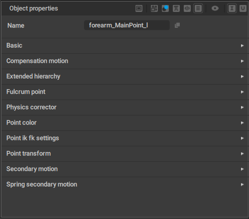
Behaviors available in Cascadeur are:
Angle Constraints
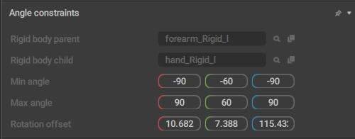
This behavior sets parameters for limiting Joint rotation when Ragdoll is used.
It is applied to Point Controllers.
Rigid body parent
Contains a link to the Rigid Body that acts as a parent object for this Point.
Rigid body child
Contains a link to the Rigid Body that acts as a child for the Rigid Body this Point is attached to.
Min angle
Sets the minimum angle to which the rig element is allowed to bend around each one of the three axes (X, Y and Z).
Max angle
Sets the maximum angle to which the rig element is allowed to bend around the same 3 axes.
Rotation offset
Sets the local rotation offset from the parent rig element. Used for aligning the Angle Constraint rotation axis to the current rig element’s orientation.
Animation Info
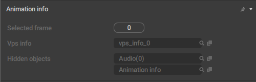
This behavior stores all data that concerns animation when the Rig Mode is enabled.
Selected frame
The number of the currently selected frame on the Timeline.
Vps info
A link to rthe VPS object.
Hidden objects
A list of objects that are not currently visible in the scene.
Attraction Point
This behavior is applied to Rigid Bodies. It defines a point that is associated with a Rigid Body and can be used to move it.
It is used during the Relaxation stage: if the Rigid Body’s position is altered (by using manipulators. for example), this point is fixed and moved so its Global coordinates would coincide with the user-defined ones.
Audio
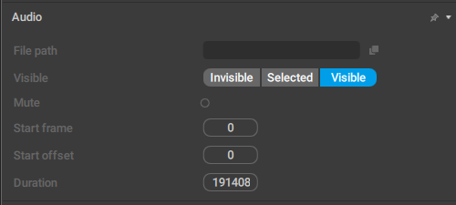
This behavior contains a set of parameters for Audio objects (that contain sound tracks that are played along with the animation).
File Path
The path to the audio file on the disk.
Visible
Affects the color used to show the audio object in the Outliner; when it is set to Visible, the color is white, for Invisible and Hidden, it’s gray.
Mute
If this is enabled, audio won’t play when the animation is played.
Start frame
Sets the animation frame from which the audio starts.
Start offset
Sets the offset (in milliseconds) for the audio. Can be used to skip the initial part of the track (if, for example, it has silence in it).
Duration
The length of the audio track in milliseconds.
AutoPhysics
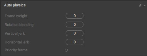
This behavior defines how a character’s Center of Mass interacts with AutoPhysics simulation.
Frame weight
This parameter controls the extent to which the algorithm tries to preserve the current frame.
By default, it is set to 0.0, meaning the original frame is not preserved.
Rotation blending
Defines how the algorithm could change the character’s rotation on the current frame.
When this value is set to 100, the character’s rotation won’t change.
When it is set to 0, the rotation angle won’t be interpolated.
Vertical jerk
Sets a limit for the vertical component of the acceleration.
This parameter is used for smoothing the Center of Mass’ trajectory. Increasing its value leads to a less smooth trajectory.
By default, it is set to zero, which is its minimal possible value.
Horizontal jerk
Same as above, but for the horizontal component of the acceleration.
Priority frame
If this is enabled on a frame, the frame is prioritized by the algorithm for this Center of Mass.
Disabled by default.
AutoPhysics Apply

This behavior controls how the AutoPhysics simulation influences the object.
Keep global rotation
Sets the extent to which the Point Controller’s rotation in the Global space is preserved during simulation.
The value of this parameter can change in the range of 0 to 100. 0 means Global rotation is not preserved and the rotation produced by the Physics corrector algorithm is used in its place. 100 means rotation is preserved completely, with no input from the algorithm.
Keep global translation
Sets the extent to which the Point’s Global translation is preserved during simulation.
AutoPosing Info
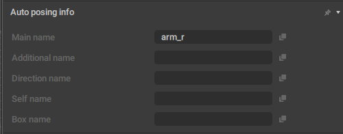
This behavior lists controllers that should be used for creating AutoPosing controllers for the object. It is used in the Rig Mode, and applied to prototype rig elements.
Main name
The name of the main AutoPosing controller associated with the object.
Additional name
The name of the additional Point associated with the object.
Direction name
The name of the directional Point associated with the object.
Self name
The name of the prototype object itself.
Box name
The name of the Box Controller associated with the object.
AutoPosing Link
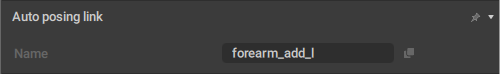
This behavior contains information for the AutoPosing tool.
It is applied to Point and Box Controllers.
Name
The name of the AutoPosing controller associated with the object.
Basic
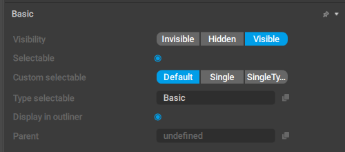
This behavior contains several standard parameters for displatying the object in the scene.
Visibility
Defines how the object is rendered in the Viewport window.
Visible - the object is rendered in the Viewport.
Hidden - the object is not rendered in the Viewport. Hidden objects can be made visible by pressing Alt + V (see Hiding Tool).
Invisible - the object is not rendered and cannot be made visible by any means other than switching this setting to some other value.
Selectable
If this is enabled, the object can be selected.
Custom selectable
Defines how the object should be selected when the selection border (link) is used.
Default means the object is always selected when it is in the border.
Single means the object is only selected when it is the only object in the border. If there are any other objects (regardless of their type), the object won’t be selected.
SingleType means the object is selected when other objects in the border have this type as well. Direction Controllers, for example, use this option.
Type selectable
This is the object type used for determining if the object should be rendered in a particular Edit Mode.
Display in outlier
If this is enabled, the object is visible on the Outliner panel.
Parent
A link to the object's parent.
Box Collision
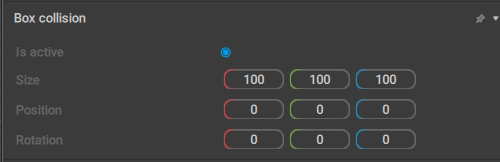
This behavior contains parameters for a Box collider.
Is active
If this is enabled, the collider is taken into account when physics simulations are run.
Enabled by default.
Size
These three values set the dimensions of the box.
Position
Sets the coordinates of the center of the box in relation to its parent.
Rotation
Sets the rotation of the collider (across three coordinate axes) in relation to its parent.
Box View
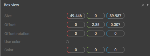
When this behavior is applied to a Box Controller, the controller is rendered as a box. By default, all Box Controllers have this behavior.
It also contains parameters that define the appearance of the box:
Size
The scale of the Box Controller across three coordinate axes.
Offset
The offset of the box controller in relation to the Point Controller it is associated with (in local coordinates).
Offset rotation
The rotation of the Box Controller across three (local) coordinate axes.
Use color
If this is enabled, a custom color (set by the Color parameter) is used to render the Box.
Color
Sets a custom color for the Box.Only has an effect when the Use color option is enabled.
Box ik
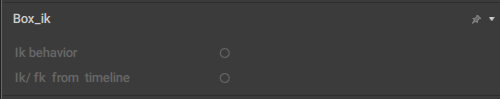
This behavior controls how Box Controllers are affected by the Kinematics algorithm.
It is exclusive to Box Controllers.
Ik behavior
If this is enabled, inverse kinematics is used for the Box Controller.
Otherwise, forward kinematics is used.
Disabled by default.
Ik/fk from timeline
If this is enabled, the type of kinematics used for the Box Controller is taken from the Timeline.
Otherwise, it is determined by the Ik behavior parameter (see above).
Also disabled by default.
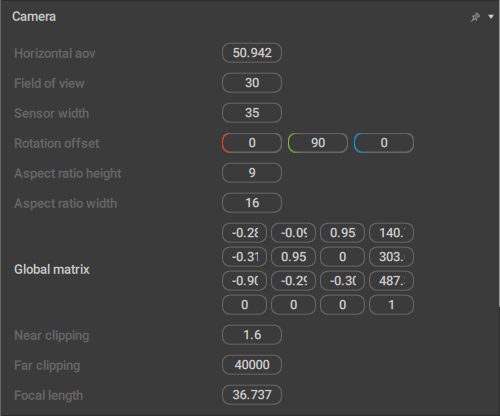
Camera
A set of parameters exclusive for Camera Objects. See the corresponding page for a detailed description.
Camera Params
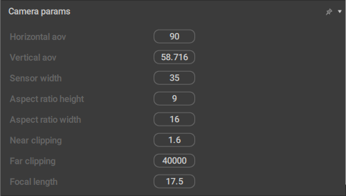
This behavior contains additional parameters for Camera Objects.
Horizontal aov
Sets the horizontal area of view (in degrees) for the camera.
Vertical aov
Sets the vertical area of view.
Sensor Width
Sets the width (in millimeters) for the virtual camera sensor.
(This is used mostly for matching live footage with 3D objects)
Field of view
Sets the field of view for the selected camera.
Rotation offset
Additional camera rotation. This parameter includes three Euler angles that can be used to change camera direction without changing its transform rotation.
Aspect ratio height
The vertical component of the proportions of the image captured by the camera.
Aspect ratio width
The horizontal component of the proportions of the image captured by the camera.
Near clipping
Sets the near clipping distance: if the distance between an object (or a part of it) and the camera is less than this value, it won't be rendered.
Far clipping
Sets the far clipping distance: if the distance between an object (or a part of it) and the camera is greater than this value, it won't be rendered.
Focal length
Sets the camera's focal length (impacts the field of view).
Capsule Collision
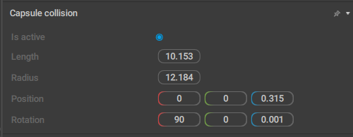
Parameters for a capsule-shaped (a cylinder with two hemispheres for caps) collider.
Is active
If this is enabled, the collider is taken into account when physics simulations are run.
Enabled by default.
Length
Sets the length of the capsule.
Radius
Sets the radius of the capsule.
Position
Sets the coordinates of the capsule’s center in relation to its parent.
Rotation
Sets the rotation of the collider (across three coordinate axes) in relation to its parent.
Center of Mass
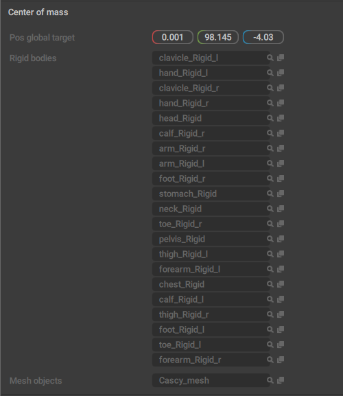
This behavior designates the object as a Center of Mass. As such, it is exclusive to CoMs and should not be added to other objects.
It also includes several parameters related to the Center of Mass:
Pos global target
Coordinates of the Center of Mass in the scene (in Global coordinate space).
Rigid bodies
A list of Rigid Bodies associated with this Center of Mass.
Mesh objects
A list of Meshes associated with this Center of Mass.
Cm mass
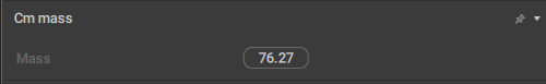
This behavior sets the overall mass of the Rigid Bodies associated with the Center of Mass.
It is specific to Centers of Mass.
Mass
The mass of the character as a whole, i.e. the sum of masses of all Rigid Bodies associated with this Center of Mass.
Circle View
This behavior is used for rendering circles.
Collisions
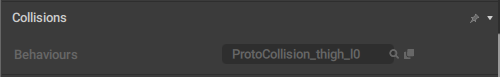
This behavior acts as a ‘container’: it contains links to collision behaviors that are attached to the objects.
It is specific for prototype rig elements, and used only in the Rig Mode.
Behaviors
A list of collision behaviors attached to the element.
Collision Material
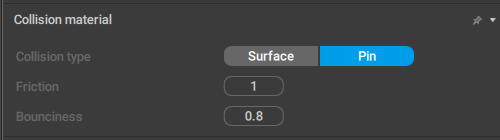
These settings define how physics simulations should work with the collider.
Collision type
Defines how the algorithm should process collisions.
There are two types of collisions:
Surface is used when the collider is supposed to interact with the floor, or with another collider. This is the default - and the most widely used - option.
Pin is used for swinging motions (when the character is supported by some kind of pin).
Friction
Sets the coefficient of friction for the collision (i.e. how fast the motion fades).
Bounciness
Sets the rebound force for the collision.
Compensation Motion
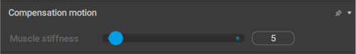
This behavior defines how the object interacts with the Compensation Motion effect.
It is exclusive to Point Controllers.
Muscle stiffness
Defines how much Compensation Motion impacts the animation.
The value of 100 means that the tool would fully preserve local coordinates of the Rigid Body associated with the point.
The value of 0 means coordinates can change completely.
For practical tasks, we would recommend to use values between 5 and 50 for body parts that should be influenced by the Compensation Motion tool.
ConnectionPointTwoBody
This behavior defines a point that links two Rigid Bodies together. All Rigid Bodies in a Cascadeur rig are connected through such points.
rigid_body_first and rigid_body_second
Links to the Rigid Bodies connected through this behavior.
pos_local_first
The point’s position in the Local coordinate space of the first body.
pos_local_second
The point’s position in the Local coordinate space of the second body.
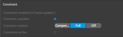
Constraint
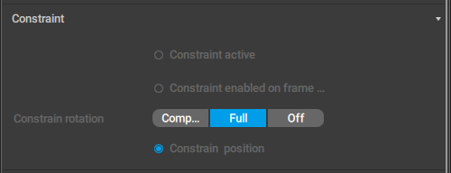
This behavior includes a number of settings for working with Constraints.
Constraint active
If this is enabled, the constraint is taken into account.
Constraint enabled on frame
If this is enabled, the constraint is active on the current frame. Can be used when you need to switch the constraint on and off between frames.
Constraint rotation
This option defines how the rotation of the constrained object is affected when the object it is constrained to is rotated.
There are three possible values:
Compensate means the position of the constrained object is affected by the rotation of the object it is constrained to, but its global rotation is not affected:
Full means rotation is copied completely:
Off means rotation is not taken into account.
Constrain position
If this is enabled, the constrained object’s position is affected when the object it is constrained to is moving.
When a transform object is constrained to another such object, this behavior has a different set of parameters:
Constraint enabled on frame
If this is enabled, the constraint is active on the current frame. Can be used when you need to switch the constraint on and off between frames.
Constrain position
If this is enabled, the constrained object’s position is affected when the object it is constrained to is moving.
Constraint rotation
This option defines how the rotation of the constrained object is affected when the object it is constrained to is rotated.
There are three possible values:
Compensate means the position of the constrained object is affected by the rotation of the object it is constrained to, but its global rotation is not affected:
Full means rotation is copied completely:
Off means rotation is not taken into account.
Constraint active
If this is enabled, the constraint is taken into account.
Finally, when a Point is constrained to a transform object, the behavior looks like this:
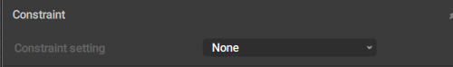
Constraint setting
Sets the Transform object to which the Point is constrained. When this value is set to None, the constraint is inactive.
Constrain View
This behavior renders a red border that designates the object as constrained.
It doesn’t have any parameters.
Convex Mesh Collision
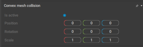
A set of settings for a convex mesh, i.e. a polygonal collider - or several such colliders - that roughly follows the shape of the selected object.
Is active
If this is enabled, the collider is taken into account when physics simulations are run.
Enabled by default.
Position
Sets the coordinates of the center of the convex mesh in relation to its parent.
Rotation
Sets the rotation (across the X, Y and Z axes) for the convex mesh, in relation to the collider’s parent.
Scale
Sets the three scaling factors (for the X, Y and Z axes) for the convex mesh.By default, all three values are equal to 1.
Custom Camera
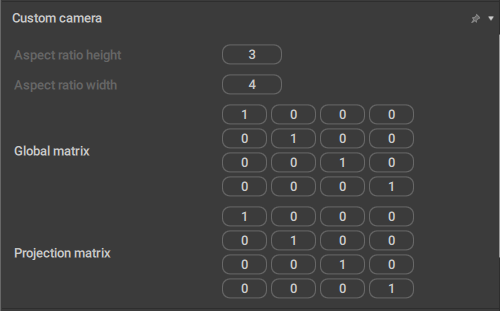
This behavior contains settings for Custom Cameras - a specific type of camera objects that use orthographic projection.
Aspect ratio height
The vertical component of the proportions of the image captured by the camera.
Aspect ratio width
The horizontal component of the proportions of the image captured by the camera.
Custom Transform Data
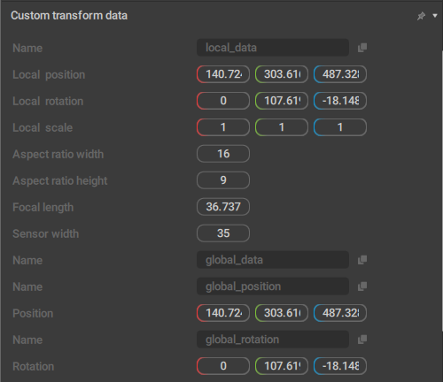
This behavior contains a custom set of data (different from the one in Transform) that is used by the Copy Tools.
The number and content of the parameters in this behavior can vary depending on the type of the object it is attached to.
Default Physics Values
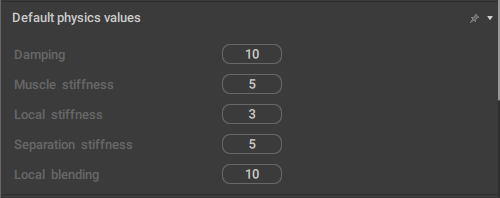
This behavior contains the default values for various physics-related parameters.
Dynamic
This is a ‘custom’ behavior where you can manually add parameters, set data types and assign values for them.
Dynamic Behavior
This behavior acts as a ‘container’ for links to other behaviors attached to the object.
Edge View
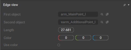
This behavior controls how Edges are rendered in the Viewport. It applies only to them.
First object
The object from which the edge starts.
Second object
The object at which the edge ends.
Length
The length of the edge.
Color
Sets a custom color for the Edge.
Only has an effect when the Use color option is enabled.
Use color
If this is enabled, a custom color (set by the Color parameter) is used to render the Edge.
Enforce Local Copy
If this behavior is applied to an object, the object’s transforms (coordinates/rotations) are copied in the local space regardless of the space chosen on the Toolbar.
It doesn’t have any parameters.
Enforce Save Data
If this behavior is applied to an object, the data for it is saved in every frame, regardless of whether the frame is a keyframe or a regular one.
It also doesn’t have any parameters.
Extended Hierarchy
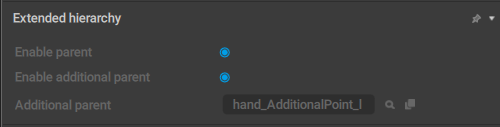
Used for attaching an additional parent to the object. This additional parent is utilized exclusively for hierarchical selection (when you double-click an object to select it along with all of its children)
Enable parent
If this option is enabled, the object is used for hierarchical selection.
Enable additional parent
If this is enabled, the additional parent (if it is present) of the selected object is used for hierarchical selection.
Additional parent
The name of the additional parent of the selected object (if present).
Fbx Export
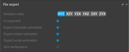
This set of options controls how Joints and Meshes are exported to the FBX format.
Rotation order
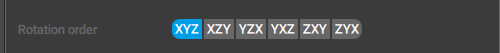
This parameter sets the rotation order used for the selected object.
When you export your animation, custom rotation order might be necessary to bypass the gimbal lock problem. This problem does not occur in Cascadeur itself because instead of Euler angles it uses quaternions for calculating rotations.
Is exported
If this is enabled, the object is exported to the FBX format. Otherwise, the object is ignored during export.
Export translate animation
If this is enabled, the object's translations (changes in its coordinates) are exported to the FBX format. Otherwise, they are ignored.
Export rotate animation
If this is enabled, the object's rotations (changes in its spatial orientation) are exported to the FBX format. Otherwise, they are ignored
Export scale animation
If this is enabled, the object's scale is exported to the FBX format. Otherwise, the scale remains constant.
Use namespaces
If this is enabled, the name of the exported object would include its namespace. This can be used when a scene has two or more identical objects (such as two characters with the same mesh), so the namespace is necessary to distinguish them.
Otherwise, the namespace is ignored.
Disabled by default.
Fixation

This behavior concerns object fixing.
Fixed
When this is enabled, the object is considered fixed.
Fulcrum Group
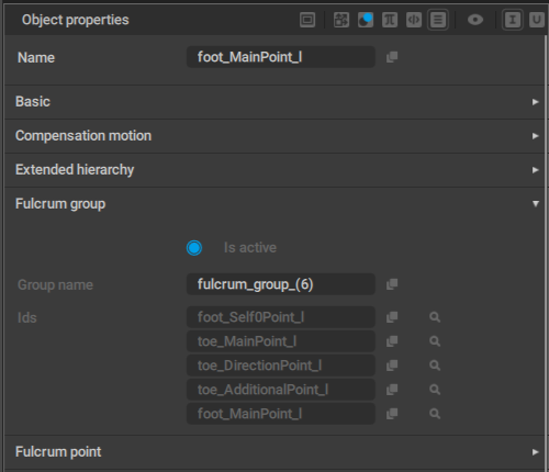
This behavior defines the group of fulcrum points.
If one of the points in the group is considered a fulcrum point, every point in the group is fixed.
This behavior is mostly used for the situations when character legs get distorted.
Is active
Defines if the group is active or not.
When this option is enabled, the fulcrum group behavior (described above) is in effect. Otherwise, it is not.
Enabled by default.
Group name
The name of the fulcrum group.
Ids
Links to the controllers included in the fulcrum group.
Fulcrum Point
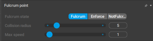
This behavior is applied to Point Controllers when they are used as fulcrum points in AutoPhysics simulations.
Fulcrum state
Sets the conditions for when the controller should be considered a fulcrum point:
Fulcrum means the controller is considered a fulcrum point when the conditions are met. This is the default value.
Enforce means the controller is always considered a fulcrum point, even when the conditions are not met.
Finally, if NotFulcrum is enabled, the controller is never considered a fulcrum point.
Max height
Sets the maximum vertical distance the Point Controller can be shifted without losing its properties as a fulcrum point.
Increasing this value can be necessary for fixing some errors in AutoPhysics simulations.
Set to 10 by default.
Max distance
Same as above, but defines the maximum horizontal shift.
Also set to 10 by default.
Graph Channels Data
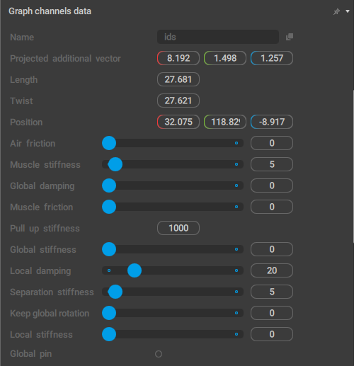
This behavior contains data that is shown in the Graph Editor.
Hinge Settings
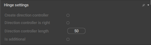
This behavior controls Hinge Connections between Rigid Bodies.
It too is only applied to prototype Rig Elements and can only be accessed in the Rig Mode.
Create direction controller
If this is enabled, a direction controller is added when a hinge connection is created for the prototype component.
Disabled by default.
Direction controller is right
This parameter should be enabled (or disabled) to flip the Direction controller.
Direction controller length
Sets the length of the direction controller.
Is additional
Should be enabled when you create a second Hinge connection in a row (i.e. when the previous prototype already has a Hinge connection).
Input Point
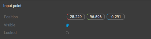
This behavior sets the parameters for AutoPosing controllers. It is exclusive for this object type.
Position
The coordinates of the AutoPosing controller.
Visible
If this is enabled, the AutoPosing Controller is visible in the Viewport.
Enabled by default.
Locked
If this is enabled, the controller is considered active and is used for generating poses.
Applies only to additional AutoPosing controllers (the ones that are initially green). Main controllers do not have this parameter.
Interpolation Controller
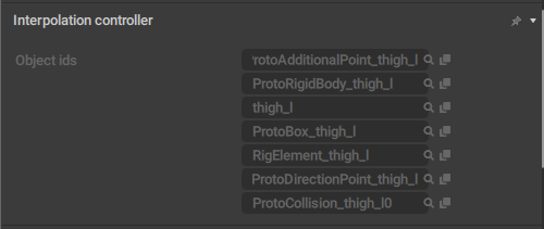
Used to interpolate the position of the constrained object based on the position of the object it is constrained to (?).
Joint
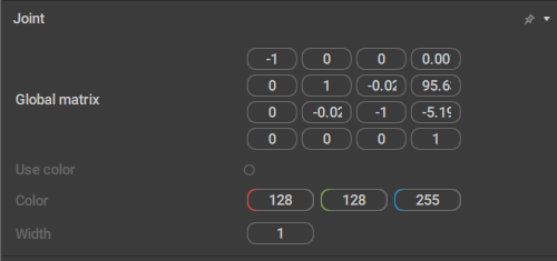
This behavior controls how a Joint is shown in the Viewport.
It can only be attached to Joints.
Use color
If this is enabled, you can set a custom color for the joint (using the Color parameter).
Disabled by default.
Color
Sets a custom color for the joint. Only works when Use color is enabled.
Width
Sets the width value for the joint.
The default value is 1.
Joint Extra Attributes
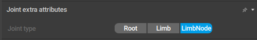
This behavior defines how a Joint is processed when the scene is exported.
It also can only be attached to Joints.
Joint type
Defines the type of the Joint for export.
There are three options available: Root, Limb and LimbNode; the latter is the default value.
In most 3d software (like Maya or Blender) this parameter is ignored, but some programs - such as Daz Studio - make use of it. In Daz in particular, the root Joint should have its Joint type set to Root, while every other Joint should be a LimbNode.
Kinematic Mesh Collision
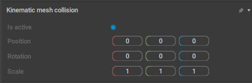
A set of settings for a Kinematic mesh: a polygonal collider that uses the object’s actual geometry for calculating collisions.
Is active
If this is enabled, the collider is taken into account when physics simulations are run.
Enabled by default.
Position
Sets the coordinates of the center of the kinematic mesh in relation to its parent.
Rotation
Sets the rotation (across the X, Y and Z axes) for the kinematic mesh, in relation to the collider’s parent.
Scale
Sets the three scaling factors (for the X, Y and Z axes) for the kinematic mesh.
By default, all three values are equal to 1.
Limb Direction
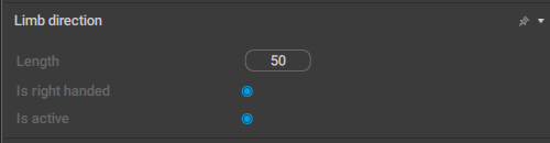
A set of parameters associated with Direction Controllers.See that page and specifically the Direction Controller Settings part for detailed descriptions of the parameters they include.
Limb Direction Data
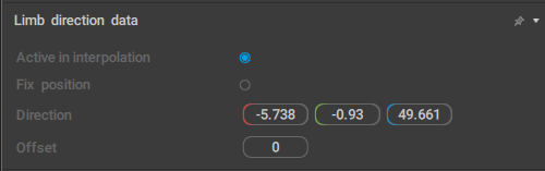
Another set of parameters for Direction Controllers.A thorough description can be found in the same section of the Direction Controllers page.
Locator
This behavior designates the object as a Locator.
Manipulator Locker
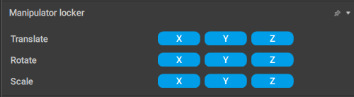
This behavior defines if a corresponding Mesh object can be translated, rotated or scaled across different coordinate axes.
Applied exclusively to Meshes.
Translate
Sets axes (X, Y and Z) along which the Mesh can be translated.
Rotate
Sets axes across which the Mesh can be rotated.
Scale
Sets axes along which the Mesh can be scaled.By default every axis is disabled; the mesh can only move along with corresponding Joints.
Mesh Object
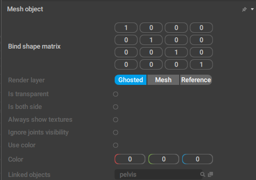
This behavior contains various parameters for Meshes.
Render layer
This defines how the mesh object is rendered in the scene:
Ghosted means the object’s Ghosts are drawn on top of the object itself (so they won’t be obscured by it).
Mesh means the object’s Ghosts are not drawn at all.
Reference means the mesh is rendered as a reference object: semi-transparent and behind all other objects.
By default, the Ghosted option is used.
Is transparent
If this is enabled, the mesh object is rendered as transparent.
Is both side
If this is enabled, the mesh object is rendered two-sided (i.e. it is always visible regardless of the view angle).
Always show textures
If this is enabled, textures applied to the mesh are always visible, event under Edit Modes (such as Point Controller Mode) where they normally aren't.
Ignore joints visibility
If this is enabled, the mesh object is not affected by hiding or unhiding Joints linked to it.
Linked objects
A list of Joints linked to the mesh.
Use color
If this is enabled, a custom color (set by the Color parameter) is used to render the Mesh.
Color
Sets a custom color for the Mesh.
Only has an effect when the Use color parameter is enabled.
Mirror
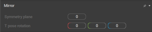
Defines how the object is mirrored.
Symmetry plane
Sets the coordinate plane used for rigging. This parameter is necessary for correctly mirroring box controller rotations.
T-pose rotation
This parameter defines how the object is rotated in its “neutral” position (the one used for rigging).
Node3d
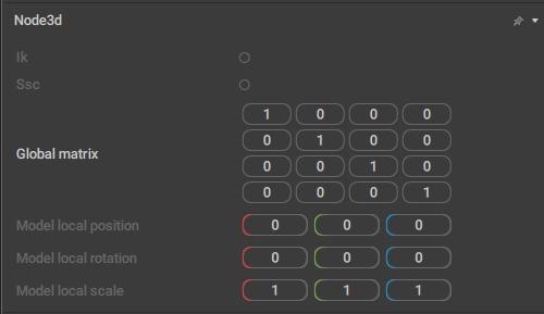
This behavior contains various parameters used for exporting scenes to external file formats.
It is applied to Joints and Meshes.
Ik
If this is enabled, the object won’t inherit transformation from its parent.
Disabled by default.
Ssc
Enabling this option activates the segmented scale compensation. It compensates the parent’s scale so the object won’t inherit it.
Model local position
The coordinates for the object in the model pose (i.e. the ‘default’ pose).
Model local rotation
The rotation values (across the X, Y and Z axes) for the model pose.
Model local scale
The scaling factors (in relation to X, Y and Z axes) for the model pose.
Physics Settings
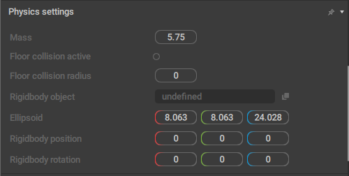
This behavior sets general physics parameters for prototype Rig Elements.
It is exclusive to such elements, and it can only be accessed in the Rig Mode.
Mass
The mass of the Prototype rigid body.
Floor collision active
If this is enabled, the rigid body won't be able to go through the ground level.
Disabled by default.
Floor collision radius
The radius used to detect when the rigid body collides with the ground.
Rigidbody object
Link to the prototype Rigid Body that is associated with this Rig Element.
Ellipsoid
The sizes for the prototype Rigid Body.
Rigidbody position
The coordinates for the prototype Rigid Body.
Rigidbody rotation
The rotation (across the X, Y and Z axes) of the prototype Rigid Body.
Pivot Customization
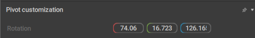
This behavior is used for setting custom pivot points. It is applied to the Point Controllers.
Rotation
Set the rotation angles (across the X, Y and Z axes).
Point

The behavior controls the Point Controller's color in Rig Mode.
Color
Sets the color of the Point using three values: the Red, Green and Blue components.
Point Color
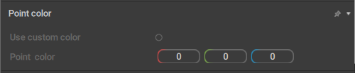
This behavior controls the Point’s color in the animation mode (i.e. outside of the Rig Mode).
Use custom color
If this is enabled, a custom color (defined by the Point color parameter) is used to render the Point.
Disabled by default.
Point color
Sets a custom color of the Point using three values: the Red, Green and Blue components.
This custom color is taken into account only when the Use custom color parameter is enabled.
Point ik fk settings
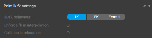
This behavior defines what kind of kinematics - forward or inverse - should be used for the Point Controller. It is also applied only to such controllers.
Ik/fk behavior
Sets the kind of kinematics to use: inverse (the IK option), forward (FK), or whatever of the two is set on the Timeline (From Timeline).
Enforce fk in interpolation
If this option is enabled, forward kinematics will be used for the point on the interpolation intervals.
Collision in relaxation
If this is enabled, the Relaxation algorithm would take collisions into account.
Disabled by default.
Point transform
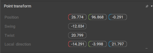
This behavior contains several parameters for Point Controllers.
It is exclusive to Points.
Position
The three values that define the position of the Point Controllers (along the XYZ coordinate axes) in the scene.
Twist
Sets the default rotation (in radians) for some body parts, such as shoulders and knees.
Swing
Sets the default bending angle (in radians) for some body parts, such as elbows and ankles.
Local direction
Sets the vector of the Direction Controller attached to the Point. Specific only to the Points that have these controllers.
Note
In Cascadeur rigs, Twist, Swing and Local direction are generally not used together.
Normally, a Point would only have one of these three parameters.
Point Update Settings
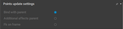
This behavior controls how Point Controllers should be updated to reflect user input.
It is applied exclusively to prototype Rig Elements and can only be accessed in the Rig Mode.
Bind with parent
If this is enabled, the prototype (and the corresponding elements of the rig) is connected to its parent in a ‘rigid’ way.
For example, a part of a character's body should be bound to its parent: if it moves, other body parts should also move accordingly.
On the other hand, a separate object (like something the character holds in his hand) should not be bound to the parent, even though it is hierarchically connected to the character.
Enabled by default.
Additional affects parent
If this is enabled, moving the Additional Controller could change the position on the rig element.
Otherwise, only rotation is affected.
In standard Cascadeur rigs, this option is enabled for the characters' heads and disabled for other elements of the rig.
Fk on frame
If this is enabled, the rig element would follow its parent object.
Mostly used for objects characters hold in their hands (tools, weapons etc.).
Polygon View
If this behavior is added to a Box Controller, the controller is rendered as a polygon.
Like Triangle View, this feature is not yet production ready and should not be used in the current version of Cascadeur.
Preserved Data
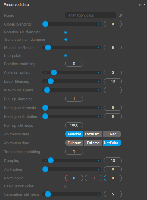
This behavior is used for saving parameters attached to the objects when the Rig Mode is enabled.
Once the Rig Mode is disabled, this behavior is used to restore the parameters it saves to their original values.
Proto Box
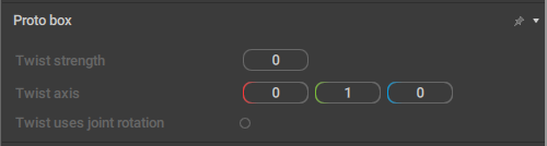
This behavior is attached to the Box Controllers that are used to control Twist joints. It contains various Twist-related parameters:
Twist strength
A value that dictates how much of the base rotation is transferred to the twist. For example, a value of 0.5 translates to 50% of transferred rotation.
Twist axis
A vector setting that dictates from which axis of the linked joint the rotation is inherited and to which axis of the twist Box controller the rotation passes.
Note that the joint and Box controllers may have different rotation orientations, so you may need to adjust the input and output axes in the twist after rig generation.
Twist uses joint rotation
When this setting is on, the twist inherits rotation from the joint that it’s linked to. If the setting is off, the rotation is inherited from the Box controller that the linked joint is rigged with, which may have an orientation that differs from the joint’s.
Disabled by default.
Qrt Info
This behavior is required for the Quick Rigging Tool to work with the character. It is attached to the Animation Info object (see the Rig Info page) and is exclusive to it.
It doesn’t have any parameters available for editing.
Ragdoll
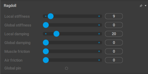
This behavior defines how the Ragdoll tool influences the object.
Local stiffness
Sets the stiffness factor for the motion in the Local space.
Global stiffness
Same as above, but for the Global space motion.
Local damping
Sets the damping factor for the motion in the Local space.
Global damping
Same as above, but for the Global space motion.
Muscle friction
Sets the friction force for the local Joint connection. Increasing this value decreases the local velocity.
Air friction
Sets the air friction force. Increasing this value slows the Rigid Body that’s attached to the Point.
Global pin
If this is enabled, the Point’s global coordinates are fixed for the simulation.
Rig Additional Info
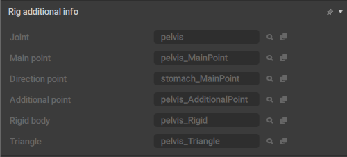
A list of rig elements attached to a prototype rig object.
Joint
A link to a Joint to which the prototype object is attached.
Main point
A link to the main point associated with the object.
Direction point
A link to the direction point associated with the object.
Additional point
A link to the additional point associated with the object.
Rigid body
A link to the Rigid Body attached to the object.
Triangle
A link to a triangle (a specific element of the rig) that is attached to the object.
Rig Info
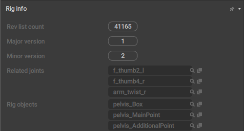
This behavior is associated with Rig Info: a special kind of scene object that contain all information regarding a character rig.
Rev list count
This is the version number of the Cascadeur executable file.
It has no effect on the Rig Info object or its content.
Major version
The ‘main’ rig version. This number is updated when major changes are made to the rig.
Minor version
The ‘secondary’ rig version. This number is updated with minor alterations to the rig.
Related joints
A list of Joints associated with this character..
Rig objects
A list of every rig element associated with this character.
Rig Version
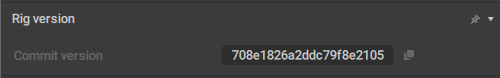
This behavior contains the hash number of the version used to generate the rig.
It is exclusive to the Rig Info object.
Rigid Body
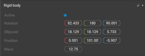
This behavior sets the parameter of a Rigid Body. For a detailed description, see the corresponding page.
Rigid Body View
This behavior is used to render Rigid Bodies in the Rig Mode
(deprecated, will be removed in the future versions)
Ruler Settings
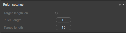
This behavior concert parameters of the Ruler object.
Target length on
When this parameter is enabled, the ruler will show if its length differs from the value set by the Target length parameter.
If the current length is greater than the Target length, the ruler’s edge will be colored red;
If it is less, the edge will be colored blue.
Ruler length
The current length of the ruler.
Target length
The target length of the ruler.
Used in combination with the Target length on parameter (see above).
Ruler Info
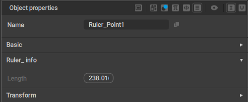
This behavior is attached to both points of the Ruler object.
Length
Specifies the distance between the points.
Secondary Motion
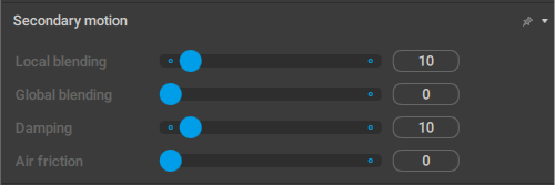
This behavior contains a set of parameters that define how the object is affected by the Secondary Motion simulation.
Local blending
Sets the force used to ‘pull’ Rigid Bodies to their original positions in the Local coordinates.
Global blending
Sets the force used to ‘pull’ Rigid Bodies to their original positions in the Global coordinates.
Damping
Sets how fast the ‘pull’ effect should fade.
Air friction
This value limits the global speed, as if wind resistance slows it down. If it is set to 0, the speed is not limited.
Separation of Motion
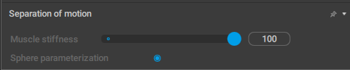
This behavior contains a set of parameters that define how the object is affected by the Separation of Motion simulation.
It is applied to Point Controllers.
Muscle stiffness
Controls how much the motion is separated for the selected Point Controller.
Sphere parametrization
?
Enabled by default.
SplineIK
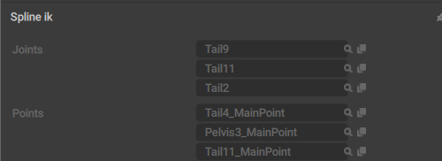
This behavior contains parameters for the SplineIK object.
Joints
The list of Joints that form the SplineIK object.
Points
The list of Point Controllers that are influenced by the SplineIK object.
SplineIK Settings
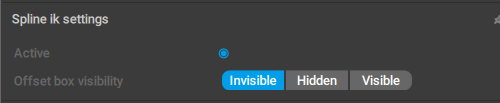
This behavior contains a set of parameters for SplineIK.
It is exclusive to the SplineIK object. This object is not visible in the Viewport, but can be found in the Outliner.
Active
If this is enabled, the SplineIK controller would affect the character’s pose.
Offset box visibility
?
Technical Links
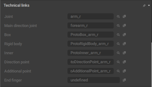
This behavior contains a list of links to prototype rig objects.
It is used in the Rig Mode, and attached to proto objects.
It is applied to prototype rig elements.
Texture Container
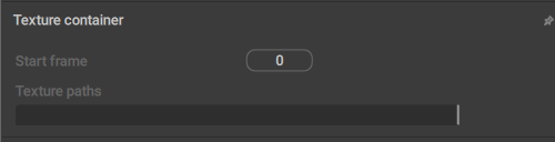
This behavior is attached to objects that have Textures (link) associated with them.
Start frame
Sets the frame from which the texture plays if it is animated, i.e. a sequence of images.
If the texture is not animated, leave this at 0.
Texture path
A path to the texture file on the disk.
Tool Fixation
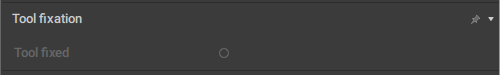
This behavior is used to fix Point Controllers using the AutoPosing tool.
It is applied to Point Controllers.
Tool fixed
If this is enabled, the Point is fixed.
Note
This behavior is rarely used in the animation workflow. Most of the time, it can be ignored.
Trajectory Customization
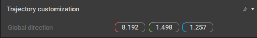
This behavior is used to set custom parameters for rendering Trajectories.
Currently, it has one parameter:
Global direction
Sets the direction (i.e. the spatial orientation) of the Trajectory object.
Transform
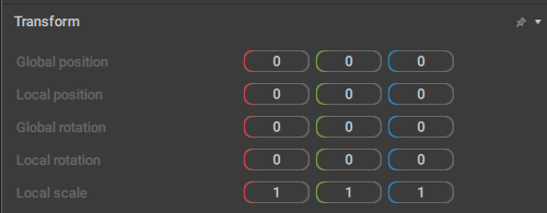
This behavior defines how the object is positioned in the scene. Most of the scene objects have this behavior (the exception being Edges and custom objects created using Node Editor).
Global position
The coordinates of the object in the global space.
Local position
The coordinates of the object in the local space in relation to its parent?
Global rotation
The rotation of the object across three global coordinate axes.
Local rotation
The object’s rotation across three local coordinate axes
This is specific for three-dimensional objects:
Local scale
The scale of the object. Specific for the objects that can be scaled:
Triangle View
When this behavior is attached to a Box Controller, the controller is rendered as a triangle.
This is an experimental feature that is not production ready and should not be used in the current version of Cascadeur.
Twist
This behavior designates an object as a Twist Joint.
It is applied to Joints and has no parameters.
Untwist
This behavior designates an object as an Untwist Joint.
It is applied to Joints and has no parameters.