Node Editor
- Home
- Tools
- Animation Tools
- Node Editor
There are times when the functions of the standard Cascadeur rigging are not enough.
For cases like these, Node Editor is used. It allows you to get to the logic behind every object in the scene - and to change it however you want.
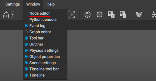
To open Node Editor:
1. Select Node Editor from the Window menu:
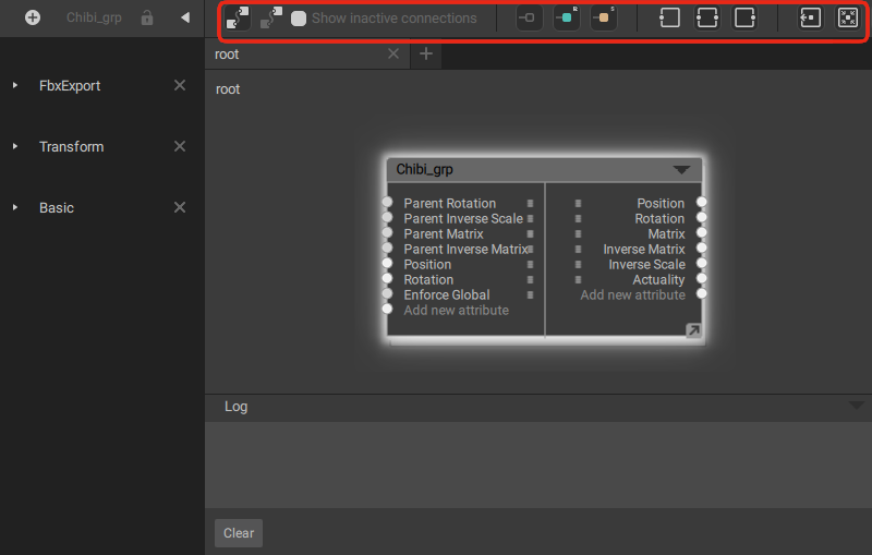
Overview
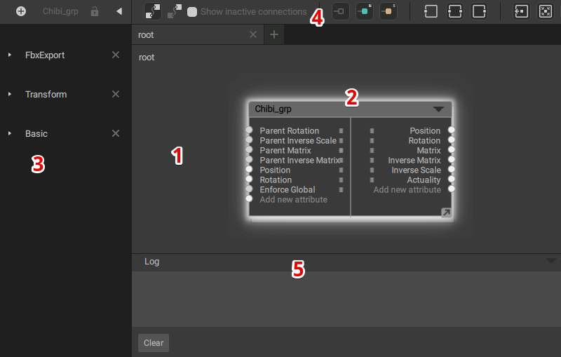
(1) Work area
Here, you can create nodes, move them around, connect and disconnect them.
(2) Node
A building block of the currently selected scene object.
(3) Node’s Behaviors
A list of behaviors associated with the selected node.
(4) View Controls
Here you can manage what nodes are visible etc.
(5) Log window
Contains a text log of the actions that transpire in the Node Editor.
Work Area
Here you can view the nodes associated with the selected scene object(s).
Navigation
Pan
1. Hold Alt.
2. Hold Left Mouse Button.
3. Move the mouse.
Zoom
1. Hold Alt
2. Rotate Mouse Wheel.
Working With Nodes
To select a node
1. Left-click it.
To move a node:
1. Place the mouse pointer over the node.
2. Hold Left Mouse Button.
3. Move the mouse.
To connect two nodes:
1. Place the mouse pointer over an output socket.
2. Hold Left Mouse Button.
3. Drag the connection line to an input socket of another node.
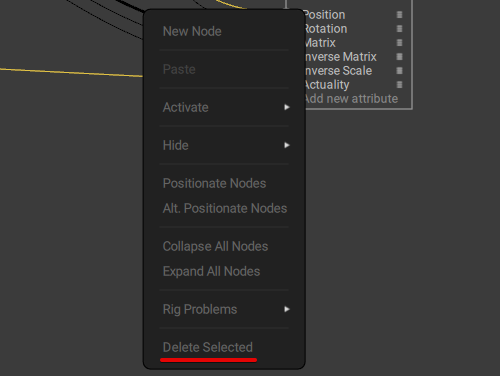
To break a connection:
1. Hold Left Mouse Button.
2. Use border select to select the connection you’d like to break.
3. Right-click the work area and select Delete selected from the menu:
Creating Objects
Sometimes you might need to add a custom object to the node setup. To do this:
1. Right-click the work area.
2. The menu will open:
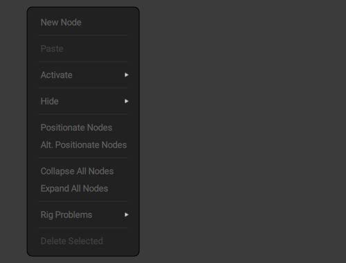
3. Select New Node this menu.
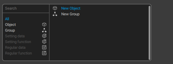
A different menu will appear. In this menu, you should select the type of object you want to create.
The selection of objects you can create differs depending on whether you are working with nodes, or with the inner structure of a node.
On the main level you can create Objects and Groups:
When you are editing the inner structure of a node, different types of objects become available:
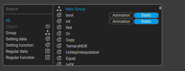
Regular data allows creating variables such as numbers, vectors, matrices and so on.
Regular function allows you to create mathematical functions for working with these regular variables.
Should be activated by Setting data to work.
Setting data allow creating logical values for activating and deactivating Regular functions.
Setting function allows you to create logical functions for working with settings.
View Controls
This panel provides means to control the work area and nodes in it.

(1) Show only active nodes
Displays only active nodes. This option is enabled by default.
(2) Show active and inactive nodes
Displays both active and active nodes.
Hidden nodes remain invisible.
(3) Show inactive connections
If this option is enabled, conncetions for inactive nodes are visible.
(4) Show incomplete connections
Shows and hides connections to 'unfinished' nodes (those which don't have ell the required connections attached and thus can't function).
(5) Show regular nodes and connections
Shows and hides regular data nodes and connections attachched to them.
(6) Show setting nodes and connections
Shows and hides setting nodes and connections attached to them.
(7) Show left connected nodes
Selects the nodes that are connected to the inputs (sockets on the left side of the node) of the currently selected nodes.
(8) Show all connected nodes
Selects the nodes that are connected to the currently selected nodes.
(9) Show right connected nodes
Selects the nodes that are connected to the outputs (sockets on the right side of the node) of the currently selected nodes
(10) Center camera on previous selected node
Focuses the view on the node to which the currently selected node is connected
(11) Center camera on all selected nodes
Focuses the view on all nodes connected to the currently selected node.
(12) Center camera on next selected node
Focuses the view on the node connected to the currently selected node.
(13) Show in scene selected objects
Shows and hides the objects selected in the scene.
(14) Positionate
Centers the camera on the selected node(s).
(15) Show hidden nodes
If this option is enabled, hidden nodes will be visible in the work area.
(16) Is interpolation
Manually sets the Is_interpolation value. Set to false by default.
(17) After physics
Manually sets the After_physics value. Set to false by default.
Log Window
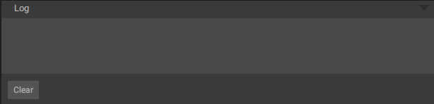
This window can be found at the bottom of the Node Editor.
It shows text logs of what’s been happening in the editor.
Log window is closed by default. It can be opened (and closed again) by clicking the triangle symbol at the right.
Node
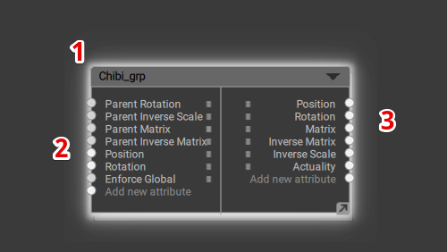
(1) Node Name
The name of the node.
(2) Inputs
The input parameters of the node.
(3) Outputs
The output parameters of the node.
Node Structure
Double-click a node to open its inner structure in a new tab:
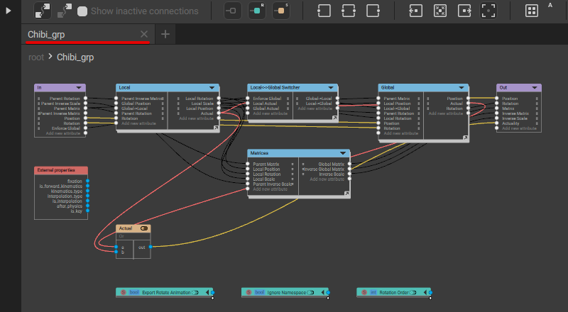
This mode shows building blocks that compose a node, and give you an option to edit them to your liking. This way you can change any property of the node.
These inner nodes can be manipulated just like regular ones.
Node’s Behaviors
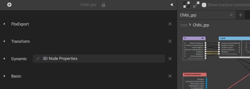
This panel shows every behavior associated with the selected node.
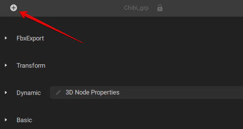
Adding Behaviors
To add a new behavior to the node:
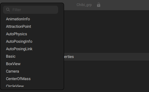
1. Click the plus sign button at the top of the panel:
2. Select a behavior from the list:
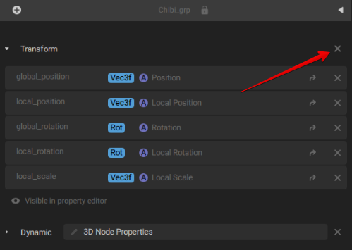
Removing Behaviors
To remove an existing behavior from a node:
1. Click the cross symbol at the right from the name of the behavior: