Elements in Rig Mode
- Home
- Rig
- Rig Structure
- Rig Elements
- Elements in Rig Mode
Prototype objects are used for generating rigs. They are created using Rigging Tool and are attached to Joints.
Note
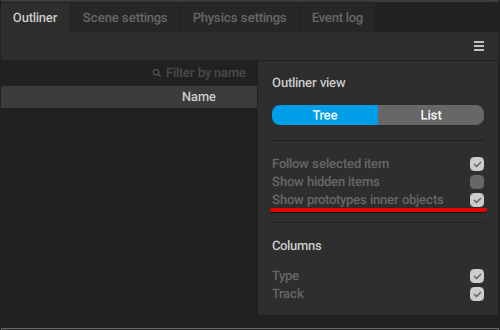
By default, prototype controllers are not visible in the Outliner, To make them visible, enable Show prototype inner objects in the drop-down menu accessed by clicking the icon at the top right corner of the Outliner panel.
When character rig is generated, these prototype objects are used to create point and box controllers, as well as rigid bodies needed for animating the character and making its movement physically accurate.
To rig a character, you need to add a set of prototype objects to every joint of the character skeleton.
Kinds of Prototype Objects
Prototype objects are created in sets. Each set includes:
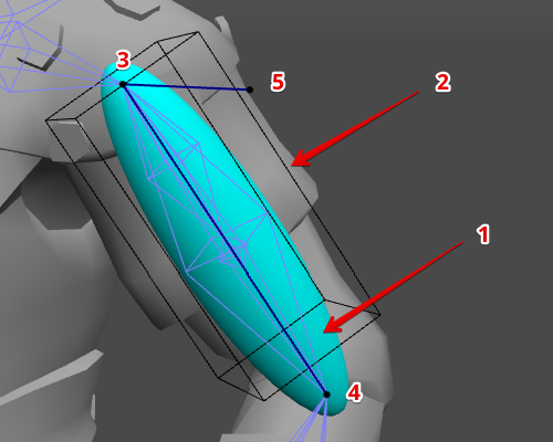
1. Proto rigid body
The main element of the set. A proto rigid body is attached to the joint (or several joints) and holds all the other objects.
When the rig is generated, a proto rigid body is used for creating a rigid body.
2. Proto box controller
The secondary element that encompasses the joint(s)
When the rig is generated, this object is used for creating a box controller.
Proto point controllers
These three elements are used for creating point controllers when the rig is generated.
3. Main point controller
Placed at the foundation of the main joint. Prototypes for Point Controller Edges connect it to two more point controllers
4. Direction point controller
Placed at the point where the main joint connects with the child joint. Its position is determined by the child joint
5. Additional point controller
Its position can be set manually using the Additional point in Axis group of parameters
Created prototypes can be selected in the Viewport window. Selecting an element in the Viewport will also select it in the Outliner window, where you can adjust its parameters.
You can also use Manipulators to adjust the positions and sizes of the prototype elements; this is not required, but can be useful in some cases.
Prototype Behaviors
There are several groups of parameters for customizing Prototype Objects. All of them can be accessed through the Object Properties panel in the Rig Mode.
Physics settings
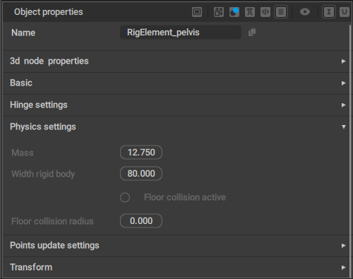
Mass
The mass of the Prototype rigid body.
Width rigid body
The width parameter for the prototype rigid body.
Floor collision active
If this is enabled, the rigid body won't be able to go through the ground level.
Disabled by default.
Floor collision radius
The radius used to detect when the rigid body collides with the ground.
Points update settings
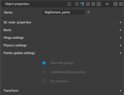
Bind with parent
If this is enabled, the prototype (and the corresponding elements of the rig) is connected to its parent in a “rigid” way.
For example, a part of a character's body should be bound to its parent: if it moves, other body parts should also move accordingly.
On the other hand, a separate object (like something the character holds in his hand) should not be bound to the parent, even though it is hierarchically connected to the character.
Enabled by default.
Additional affects parent
If this is enabled, moving the Additional Controller could change the position on the rig element.
Otherwise, only rotation is affected.
In standard Cascadeur rigs, this option is enabled for the characters' heads and disabled for other elements of the rig.
Fk on frame
If this is enabled, the rig element would follow its parent object.
Mostly used for objects characters hold in their hands (tools, weapons etc.)
Hinge settings
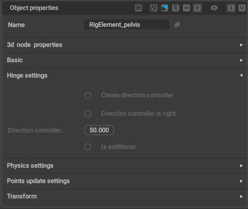
Create direction controller
If this is enabled, a direction controller is added when a hinge connection is created for the prototype component.
Disabled by default.
Direction controller is right
This parameter should be enabled (or disabled) to flip the Direction controller.
Direction_controller length
Sets the length of the direction controller.
Is additional
Should be enabled when you create a second Hinge connection in a row (i.e. when the previous prototype already has a Hinge connection).