Nodes Overview
- Home
- Tools
- Animation Tools
- Node Editor
- Nodes Overview
The Node Editor included in Cascadeur features many nodes designed for a variety of tasks. On this page we will be taking a look at all of them, their parameters and purposes.
Object Nodes
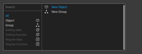
These nodes are available in the Node Editor work area, on the tab titled root.
New Object
This option creates a new empty object.
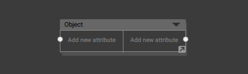
An empty object.
By default, an object has no input or output parameters. They have to be added manually.
To add a parameter:
1. Select the node.
2. Right click the Add new attribute line.
To remove a parameter:
1. Select it with the Right Mouse Button.
2. Set an empty name.
Newly created parameters are automatically assigned names like ‘New attribute 1’, ‘New attribute 2’ and so on.
If you need to use a custom name for a parameter:
1. Right-click the name of this parameter.
2. Enter the new name.
Alternatively, you can connect the parameter to an already existing parameter. In this case, the name of that parameter will be used.
Objects in the Node Editor act as representations of the objects in the scene.
An object includes:
- A list of Behaviors (attached to the object.
- A set of inner nodes (see below) for working with behaviors and their parameters.
- (optional) One or more Groups that store aforementioned inner nodes. Groups do not affect the object’s workflow in any way; they are only used to make its structure more visually comprehensible.
This inner structure of an object can be viewed by double-clicking it
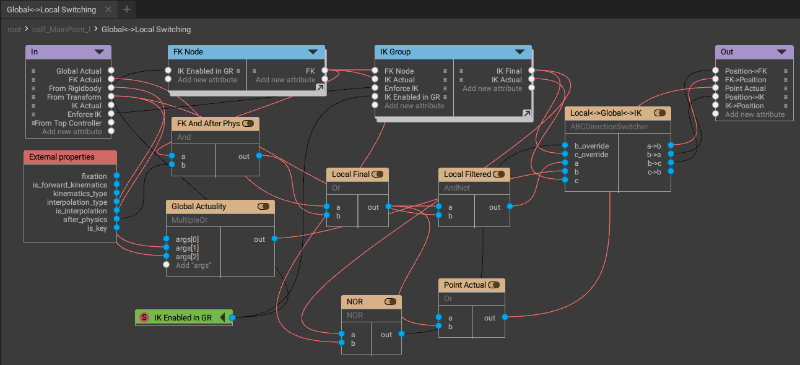
Inner structure of an object, shown in a dedicated tab.
The structure of any node includes several standard elements:
In
The list of the node’s input parameters.
External properties
Another set of input parameters:
fixation
A boolean value that shows if the object is fixed (link) or not. True if the object is fixed, false if it isn’t.
ik_fk
A boolean value that indicates what kind of kinematics is used on the current keyframe or interval.
True when forward (FK) kinematics is used. False when inverse (IK) kinematics is used.
interpolation_type
The type of interpolation on the current frame.
True when any interpolation type other than Bezier is used.
False when Bezier interpolation is used.
is_interpolation
True if the update is called during interpolation; false if it is called during any other change (using manipulators, Tween Machine etc.).
after_physics
Shows the state of the scene update process (link):
True if relaxation has already been applied to the object. False if relaxation has not yet been applied.
is_key
A boolean value that defines if the current frame is a keyframe (link).
True if the current frame is a keyframe, false otherwise.
Out
The list of parameters the node passes to the next node.
Group
Creates a new group: a collection of nodes that is treated as a single node in the work area.
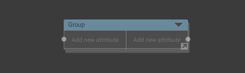
An empty group in the working area.
A group includes:
- Input parameters: a set of external values that are transferred to the group to perform some operations with.
- Output parameters: another set of values the group passes to the next node (or nodes).
- Inner nodes: a node setup for performing operations with numerical values, often with the values received from the Input parameters.
To open a group, double-click it. The group will open in a new tab.
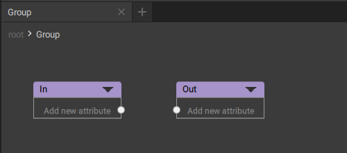
An empty group.
A newly created group only has two standard elements:
In
Contains Input parameters for the group.
Out
Contains Output parameters for the group.
Inner Nodes
These nodes make up inner structures of Groups and Objects. To open this structure, double-click an object node in the Node Editor work area. The inner structure of the node will be shown in a separate tab.
While on this tab, you have access to a different set of nodes you can create and manage:
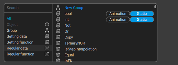
New Group
Creates a container for storing nodes, just like on the root level.
Other nodes can be divided into two distinct categories: Regular nodes (used for performing mathematical operations) and Settings (used for performing logical operations and determining which Regular nodes should be activated).
Setting nodes are executed before Regular nodes.
Setting data
A set of options for creating setting values: numerical and boolean constants that can be used for activating parts of the Regular data graph (see below) they are connected to.
These values cannot be changed as the node graph is being executed. They should be defined beforehand.
Int

A simple numerical value.
This node has only one parameter: an integer number. The number equals to zero by default and can be set manually.
Bool

A boolean value.
This node also has only one parameter: its value. It can be either true or false.
Setting function
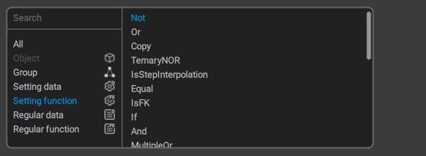
Logical functions (OR, AND etc.) for working with setting data.
Some - but not all! - of these functions are described in the list below:
If
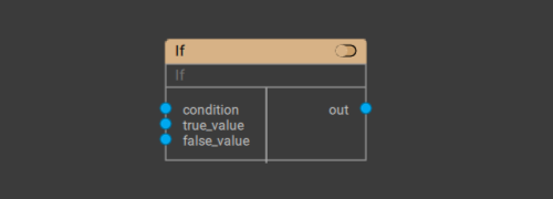
A simple logic gate.
Outputs true_value if the condition is true and false_value if it is false.
Or

An OR logic gate.
Outputs 1 if either A, or B, or both of them are correct. Outputs 0 if neither is correct.
Not

A NOT logic gate.
Outputs 1 if the argument is 0, and 0 if it is 1.
NOR

A NOR logic gate.
Outputs 1 when both A and B are equal to 0. Outputs 0 when at least one of them is 1.
And

An AND logic gate.
Outputs 1 if both A and B are 1. Outputs 0 if at least one of them is 0.
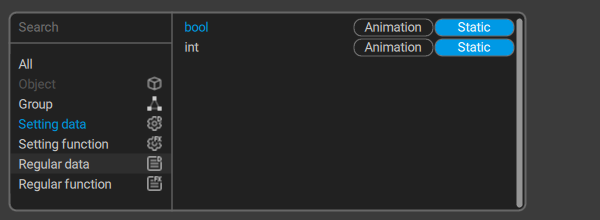
Regular data
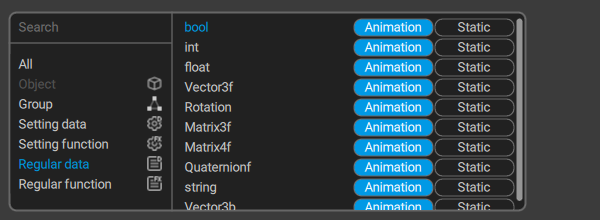
Allows creating variables such as numbers, vectors, matrices and so on.
Unlike Setting Data, these variables are able to receive values from other nodes.
A regular data value can belong to one of two types: Animation and Static:
-Animation means that the data stores a separate value for each frame.
-Static means that the value is the same for every frame (but it can still be changed using function nodes).
Bool

A Boolean variable.
Int
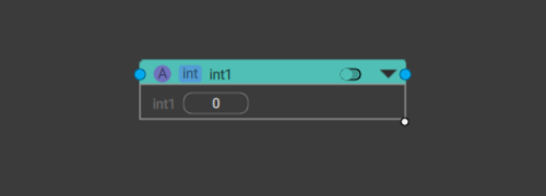
An integer variable.
Float
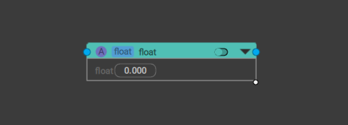
A floating point variable.
Vector3f
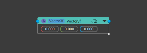
A three-dimensional vector.
Includes three Float variables that represent the vector’s coordinates.
Vector4f
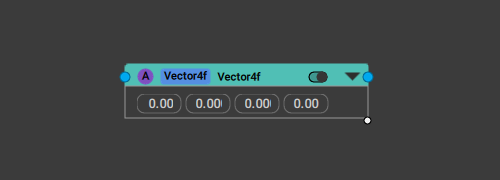
A four-dimensional vector.
Made up of four Float variables that represent the vector’s coordinates.
Rotation
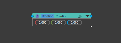
A variable that represents rotation.
It includes three Float variables each one of which defines the rotation across corresponding axis.
Matrix3f
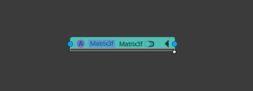
A 3 by 3 matrix.
Matrix4f
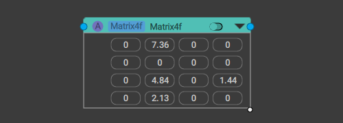
A 4 by 4 matrix.
Quaternionf
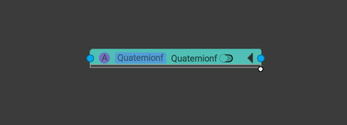
A quaternion value.
String
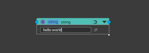
A string, as in a succession of symbols.
Regular function
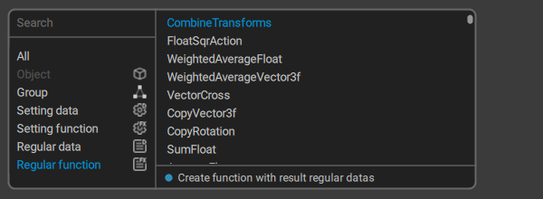
These are functions for performing operations with regular variables.
Keep in mind that using regular functions has some nuances:
1. In order to work, a regular function has to be activated. Otherwise, it won't work.
2. A regular function is activated by plugging a value outputted by a setting function to its Activity input.
If this value is True, the regular function will be activated. This is how setting functions are used to decide which parts of the regular data graph should be activated.
3. You can't simply plug one regular function to another.
If you need to work with a value outputted by a regular function, you have to first write it to a regular data.
Some of the more often-used functions are described below:
IfFloat
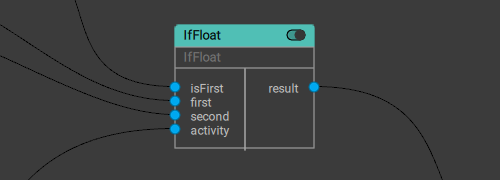
A Float-based logic gate.
Returns one of the two (firstVal and secondVal) values depending on the value of the isFirst condition:
If isFirst is True (1), firstVal is returned.
If it is False (0), secondVal is returned.
IfVector3f
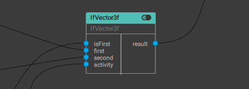
A vector-based logic gate.
Returns one of the two (firstVal and secondVal) values depending on the value of the isFirst condition:
If isFirst is True (1), firstVal is returned.
If it is False (0), secondVal is returned.
IfRotation
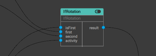
A Rotation-based logic gate.
Returns one of the two (firstVal and secondVal) values depending on the value of the isFirst condition:
If isFirst is True (1), firstVal is returned.
If it is False (0), secondVal is returned.
RotateVector
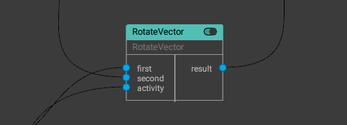
Rotates the first given vector (the second value) by an angle defined by the given rotation (the first value).
FloatToVector3
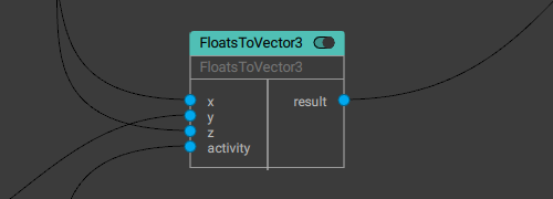
Combines a vector out of 3 Float values.
FloatsToVector4
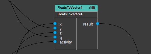
Combines a vector out of 4 Float values.
Vector3ToFloats
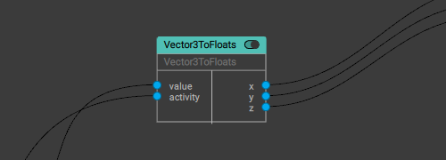
Breaks the given vector into three Float values.
Vector4ToFloats
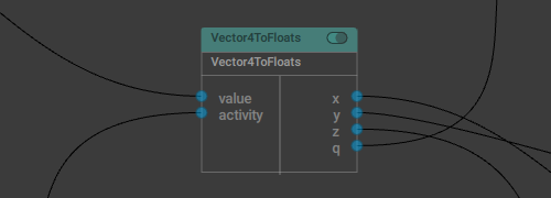
Breaks the given vector into four Float values.
Vector3ToVector4
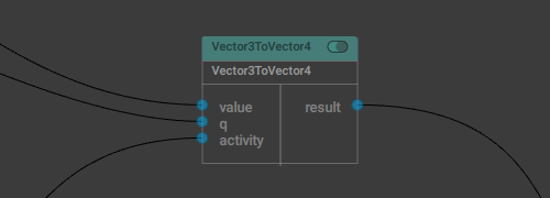
Combines a four-dimensional vector from a three-dimensional vector and a Float value.
Vector4ToVector3
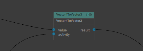
Converts a four-dimensional vector into a three-dimensional vector by removing the fourth component.
SubtractFloat
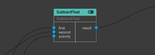
Subtracts one Float value from another.
SumVector3f
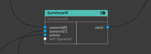
Returns the sum of the given three-dimensional vectors.
ScaleVectorToLength
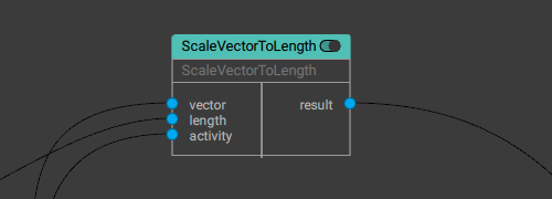
Scales given vector to the given length.
Length is a Float value.
Matrix3Mul
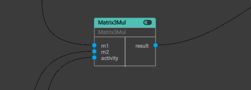
Outputs the product of two given 3x3 matrices.
MultMatrix4f
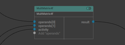
Outputs the product of several (two or more) given 4x4 matrices.
SubtractVector3f
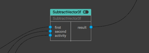
Subtracts one three-dimensional vector (the first value) from another (the second value).
VectorLength

Returns the length of a given vector.