Rigging Tools
The process of creating a rig involves placing and adjusting sets of Prototype objects. These prototype objects are attached to joints of the character's skeleton and are used to generate the actual rig.
While the rig itself is generated automatically, its quality depends on the quality of the prototype. Creating a good prototype requires choosing right positions for its elements.
Every instrument for creating and managing prototype objects is located on the Rigging tools panel.
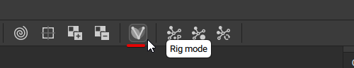
To open this panel, click the Rig mode button on the Toolbar:
Warning
If the character already has a rig attached, this rig will be deleted when you enter the Rig mode, and replaced with corresponding Prototype objects, which you can then edit.
Also, when the Rig mode is enabled, the character will be reset to the default pose (usually the T-pose for humanoid characters).
Animation and the Timeline will not be available, but they won't disappear. Once you leave th Rig mode, animation data and the access to the Timeline will be restored.

Quick Rigging Tool
Clicking this button opens the Quick Rigging Tool: a dedicated instrument for quickly creating humanoid rigs.
Add Group
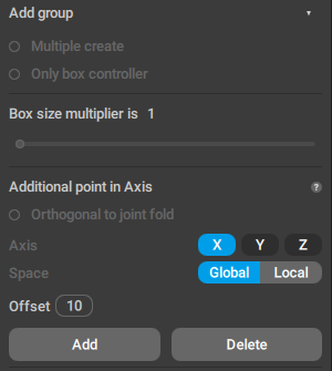
This group contains tools for creating and removing prototype rig elements.
Multiple create
If this is enabled, a separate set of prototype rig elements is created for every selected joints.
Only box controller
If this is enabled, only a prototype Box Controller is created for the select Joint(s).
Box size multiplier
Increases the size of the prototype Box Controller.
The value can change from 1 (no increase in size) to 20.
Additional point in Axis
This group of parameters controls the position of the additional point controller.
Orthogonal to joint fold
When this option is enabled, the third controller will be placed at the bending axis between the main selected joint and its parent joint. Used for creating limbs such as arms and legs

An additional point controller lying on the bending axis between two joints
This option only works when character limbs are bent by default (so the bending axis can be calculated). If the limbs form a straight line, it will not work. In this case, it is recommended to use joints to slightly bend the limbs.
When this option is selected, an axis (see the next parameter) for the additional controller cannot be specified.
Axis
Allows you to set an axis (X, Y or Z) on which the additional controller is lying:
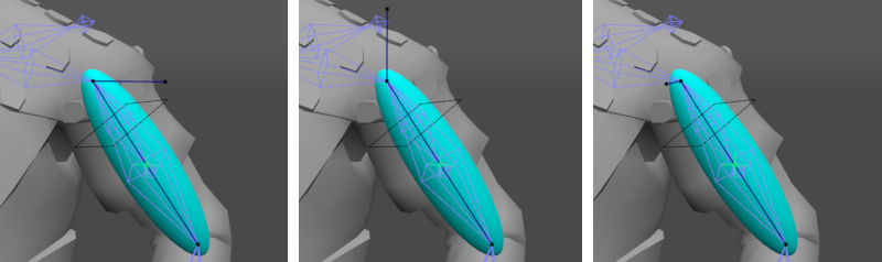
Position of the third controller on the X (left), Y (middle) and Z (right) axes. The rigid body is hidden from view
Space
These radio buttons define whether the axis on which the additional controller is lying should be Global or Local
Offset
This parameter determines the distance between the main point controller and the additional point.
Prototype rig elements can be viewed in the Outliner window. There, you can edit their properties such as mass for rigid bodies.
Add
Clicking this button creates a new set of prototype rig elements and binds them to the selected joint.
To learn about creating rigs, see our How to rig in Cascadeur tutorial.
Delete
Deletes selected rig element(s).
Joint Actions

This tab contains tools for performing various operations with Joints.
For convenience, it is separated into two parts:
Standard Joints
These tools are intended for working with regular Joints.
Add
Creates a new Joint at the end of the currently selected Joint.
Delete
Removes the currently selected Joint.
Note
Joints created using these tools won’t affect the skinning data and thus won’t have any direct effect on the animation.
Virtual Joints
This is a set of tools for working with Virtual Joints.
Such Joints are mostly used for creating extra Additional Controllers.
For Virtual Joints, only Box Controllers can be created as elements of the rig. Trying to create other rig elements for them would lead to errors.
Don't forget to enable the Only box controllers option when rigging them.
Add
Creates a new virtual joint at the end of a currently selected Joint.
Delete
Removes a currently selected virtual joint.
Snap Rig
Snaps a Point Controller to a Virtual Joint.
- Select a Point Controller.
- Select the Joint you’d like to snap it to.
- Click the button.
Snap Joint
Snaps a Virtual Joint to a Point Controller.
- Select a Virtual Joint.
- Select the Point Controller you’d like to snap it to.
- Click the button.
Collision

This section contains tools for working with collision shapes.

Collision shapes in the character rig.
Add
Creates a collision shape for the selected Joint.
When you click this button, you'll be asked to choose a type for the shape:

Remove
Deletes the collision shape from the selected Joint.
Mirror

This tab contains settings for creating mirror copies of prototype objects.
Note
Mirror plane is placed at the position of the parent of the selected object.
Plane
Sets the mirroring plane.
Local joint position
Enabling this option binds mirrored prototypes to the joints. Can be used when positions of the character's limbs are not fully symmetrical.
Original and Mirrored
These fields should contain parts of the Joints' names that can be used to distinguish whether the Joint is located on the right or the left side of the character.
Original is intended for the side you are planning to rig manually (for example, if you’re creating the left arm, this field should contain the differential part for the joints on the left).
Mirrored is for the mirrored limb(s). (in the above example, it should contain the differential part for the joints on the right).
Create mirror object
By clicking this button, you create a mirrored copy of every prototype that can be mirrored.
Warning
As shown in the example, Straighten to hinge offsets the Rigid Bodies without moving their respective Joints. Because of this, using it might affect the way these Joints bend.
Use this option with care and only when necessary.
Hinge Actions

Union to hinge
Creates a Hinge Connection.
1. Select Additional Points for several rig elements.
2. Click the Union to hinge button.
This will create a hinge connection along with a Direction Controller (link) for the hinge.
Ortho hinge
Makes the hinge orthogonal to the line that connects the Main Controller with the Main Direction Controller (in case it is not).
1. Select both of the hinge controllers.
2. Click the Ortho hinge button.
Straighten to hinge
Allows you to manually set the bending axis in case it wasn’t correctly defined by the software.
1. Select both points around the hinge connection.
2. Move/rotate the selected points to set a new direction for the Direction Controller.
3. Once you have an appropriate direction, click the Straighten to hinge button.
Note
Changing the bending axis can offset Rigid Bodies in relation to their respective Joints.
This in turn might lead to abnormalities in animation, so use this function with care and only when necessary.
Main Actions

This panel contains functions for creating additional rig elements.
Clear animation data
Removes certain kinds of data (such as point color, fulcrum group activity or physics information) from the character's animation.
Prototype center of mass
Creates and removes additional Centers of Mass.
To create a center of mass:
1. Select a prototype rigid body.
2. Click the Add button.
This option can be used when your rig requires more then one center of mass (for example: one for the character and another for the weapon the character holds).
Twist
Applies a 'Twist' behavior to the selected Box controllers.
For it to work, you need to select one Box controller (the one that inherits the twist rotation) and one Joint (the one that transfers twist rotation).
Used for rigging Twist Bones.
Untwist
Applies an 'Untwist' behavior to the selected Rig element.
To use it, you need to select a parent Rig element, a child element, and the target element, in that exact order.
Used for limiting the twist rotation of specific limbs, such as the upper arm.
Prototype fulcrum group
Adds or removes selected points to a Fulcrum group.
Points combined into a fulcrum group behave like a single point. This is useful when the character’s feet have a complex structure and multiple points and rigid bodies. Combining these multiple points into one fulcrum group produces more natural behavior, especially with tools like AutoPhysics.
Spline IK
Used for creating curves for controlling joint chains.
This feature is described in greater detail on the Spline IK page.
Root constraint
Adds or removes the Root constraint to the selected objects.
This feature is described in greater detail on the Root constraint page.
Additional Actions

This set of functions is used for creating and removing additional parts of the character skeleton.
Point controller
Creates and removes additional Point Controllers.
To create a point controller:
1. Select a Rigid Body.
2. Click the Add button.
The newly created point controller will be linked to the selected rigid body.
To remove a Point controller:
1. Select a Point Controller you’ve previously created.
2. Click the Remove button.
Additional box
Add and removes additional Box Controllers
Additional box controllers are not used for controlling rotations and animating the character, like regular box controllers would be. These are helper objects that are used for more clearly visualizing the trajectories of the regular box controllers to which they are linked.
To create an additional box controller:
1. Select a rig element
2.-Click the Add button
A new Box Controller should appear. This controller will be linked to the rig element you’ve selected.
To remove an additional box controller:
1. Select a Box Controller
2. Click the Remove button
This works only for Box Controllers you’ve created with the Add button. If you need to delete a regular Box Controller (or any other element of the rig), use the Delete rig element button instead.
Custom additional point
Designates a user-selected Point Controller as an additional point.
1. Select a Point Controller.
2. Click the Set button.
The same tab can also be used to disable an existing additional point:
1. Select the point.
2. Click the Remove button.
After this, the selected point will no longer act as an additional controller, and will not influence the character mesh in a way an additional point would.
This feature is mostly used for rigging heels.
Additional joint
Used for attaching and detaching joints to the selected proto element.
Using this option, you can assign an element of the rig to control joints other than the ones it is attached to by default.
Additional parent
Adds rig parts to the hierarchical selection.
1. Select two prototype elements.
2. Click the Add button.
3. Choose which one will be the parent.
Now when you select an object and all its children (by double-clicking it), the additional parent and all its children will also be selected.
This only affects selection. The elements of the rig are not connected in any other way.Custom rotation
Sets an object from which the point controller would receive the directions of the coordinate axes for the Manipulators in the Local mode.
1. Select two rigid bodies.
2. Click the Add button.
3. Choose the rigid body from which the direction will be transfered.
Autoposing props
This button creates AutoPosing controllers for the selected Rigid Body.
Should be used when you need to add some kind of prop (an object attached to the character) to the AutoPoisng setup.
See the AutoPosing page to learn how to use it.
Import/Export

Contains various options for working with JSON files
Set hierarchy by joints
If this option is enabled, the hierarchy of an imported rig is changed to coincide with the hierarchy of the joints.
If it is disabled, the hierarchy from the .rigcasc file (the file containing imported rig) is used instead.
To selected
If this is enabled, the rig imported from a JSON file is applied only to the selected joints.
With T-pose
If this option is enabled, the pose in the scene is ignored, and the pose from the JSON file is used instead.
If it is disabled, the pose in the JSON file is ignored instead; the proto components are applied to the pose in the scene.
If you re-save the JSON file with this option disabled, the pose in the file will be overwritten with the pose from the scene.
Use this when the character pose in the JSON is different from the one in the scene, and you don’t want to mix them.
Import
Imports rig data from a JSON file (saved by the previous option) and applies it to the character.
Export
Saves existing rig elements to a JSON file. This file can later be used to apply rig data to a character.
Character Mirror Plane

Here you can set the plane of symmetry for the character. Required for the Mirror Tools to work properly.
Create autoposing

If this option is enabled, AutoPosing controllers are generated along with the rig (meaning you can use AutoPosing immediately after the rig is finalized).
Otherwise, AutoPosing controllers will be generated only once the corresponding Edit Mode is enabled.
Generate rig

Clicking this button converts all proto rig elements to parts of an actual rig and links them to the character skeleton.