Physics Corrector
- Home
- Tools
- Physics Tools
- AutoPhysics
- Physics Corrector
This is a tool that analyzes the animation you’ve created and suggests a physically accurate version of it.
Being a part of the AutoPhysics family of instruments, Physics Corrector plays a crucial role in calculating AutoPhysics simulations.
Enabling Physics Corrector
As Physics Corrector provides the cventral part of AutoPhysics simulation, it is enabled by default.
However, you can enable (if it was disabled for some reason) or disable (if you don't need it in your simulation) manually:
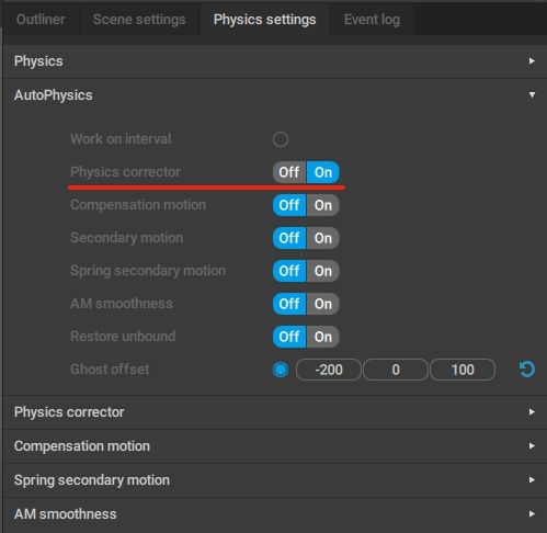
1. Go to the AutoPhysics tab on the Physics settings panel.
2. Turn on (or turn off) the Physics Corrector option:
After this, you should see the effect on the simulation.
How It Works
Physics Corrector can alter an animation in a few ways:
- For intervals without fulcrum points, it creates ballistic trajectories and move the characters along them.
- For intervals with fulcrum points, it smooths out the vertical part of the movement and alter the horizontal part to achieve dynamic balance and make the motion appear more stable.
The tool also takes into account priority frames:
- On ballistic intervals, setting a frame as a priority frame increases its weight and allows for retaining the character's rotation on this frame.
- On regular intervals, priority frames keep character's rotation instead. Large numbers of priority frames might lead to issues, as the algorithm won't be able to find a fitting solution.
Physics Corrector Settings
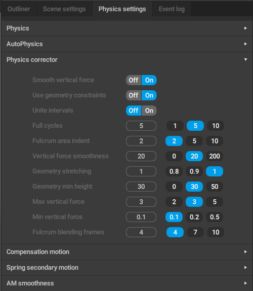
If you need more precise control over AutoPhysics simulation, parameters for this can be found under the Physics corrector tab:
Smooth vertical force
If this is enabled, the vertical (the Y axis) movement of the character is smoothed for the AutoPhysics simulation.
Use geometry constraints
Limits the position of the character’s Center of Mass depending on the length of the character’s legs.
Unite intervals
If this option is enabled, smaller intervals are combined into bigger ones; the Physics Corrector algorithm is then applied to these bigger intervals.
Should be used when resulting trajectory is not smooth enough.
Disabled by default.
Full cycles
Defines how many times the tool should simulate snapping the character to the AutoPhysics ghost.
Increasing the number of cycles improves the accuracy of the calculation. However, this also slows the tool down.
This parameter can be either set manually or using one of the pre-defined values (1, 2 and 5). The default value is 5.
Fulcrum area indent
How much the fulcrum point is increased.
Used in situations when the corresponding parts of the character mesh happen to be bigger than the “default” size of the fulcrum point(s) calculated on the basis of the Point Controllers.
The default value is 5.
Vertical force smoothness
This parameter defines how much the vertical (the Y axis) movement of the character is smoothed for the AutoPhysics simulation. The higher this value is, the more linear the trajectory will be.
The same animation with Vertical Force Smoothing set to 50 (up) and to 200 (down).
Set to 20 by default.
Geometry stretching
Sets how much the simulation is able to straighten limbs. The default value of 1.0 means that limbs can be made completely straight.
Geometry min height
Sets the limit for the height (the Y coordinate) of the Center of Mass.
Max vertical force
The value of the force of gravity is multiplied by this coefficient to determine how fast the force applied to the character can change. If the force exceeds the resulting value, it is filtered by the Y axis.
How much the force is filtered is determined by the Vertical Force Smoothing parameter.
This parameter can be either set manually or using one of the pre-defined values (2, 3 and 5). It is set to 3 by default.
Min vertical force
Defines the minimal force applied to the character from the fulcrum point, and with it, how fast the character can descend.
The value can range from 0 to 1. If it is equal to 1, the character cannot descend. The closer the value to zero, the higher is the speed of descension. However, decreasing this parameter can sometimes affect the stability of the simulation.
Used for vertical filtering.
Set to 0.1 by default.
Fulcrum blending frames
The number of frames used for smoothly interpolating the objects to the position(s) they should have at a fulcrum point.
This kind of interpolation is necessary because physical simulations are not applied to the character outside of the fulcrum point frames. Instead, only the Center of Mass trajectory is adjusted, and the character moves as a whole. In some situations, this might distort the positions of the limbs, if they end up too far from the corresponding fulcrum points.
To fix this issue, limb positions are additionally interpolated on several frames that precede the fulcrum point.
Physics Corrector Behavior
If you need to adjust how Physics Corrector works with an individual Point Controller, you can do so using a dedicated group of parameters associated with this controller.
These parameters are found on the Object properties panel, under the Physics corrector tab:
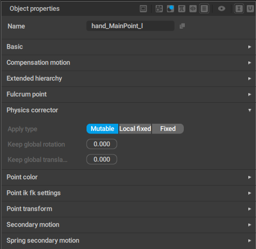
Apply type
Defines how exactly the Physics Corrector algorithm is applied to the Point Controller.
- Mutable means the point can change its position under the influence of the algorithm.
- Local fixed means the point always retains its position in the Local space.
- Fixed means the point ratains its position in the Global space.
Keep global rotation
Sets the extent to which the algoritm should preserve the object's global rotation.
When this paramter is set to 100, rotation is preserved in its entirety; when it is set to 0, rotation is not preserved.
By default, it is set to 0.
Keep global translation
Same as above, but for translation.
This paramter is also set to 0 by default.
Physics Corrector also takes into account the Auto physics group of parameters associated with the Center of Mass:
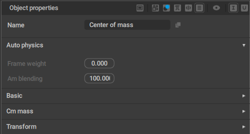
Frame weight
This parameter controls the extent to which the algorithm tries to preserve the current frame.
By default, it is set to 0.0, meaning the original frame is not preserved.
Am blending
Used for interpolating rotation.
When Am blending is set to 100, the character won’t change the rotation on the corresponding frame.
When it is set to 0, the rotation angle won’t be interpolated.
Its default value is 100. For real-life scenarios, it is recommended to keep Am blending in the range of 0 to 90.
Common Issues
Feet Distortions
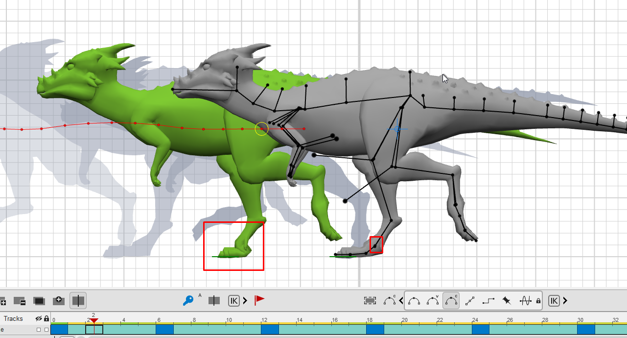
If the character’s feet include several Rigid Bodies and subsequently several Point Controllers, some of these points might not be designated as Fulcrum Points. Because of that, they might shift along with the Center of Mass, causing distortions seen above.
To fix this issue:
1. Go to a keyframe after the frames where the issue occurs.
2. Enable Enforce for the points that should not move:
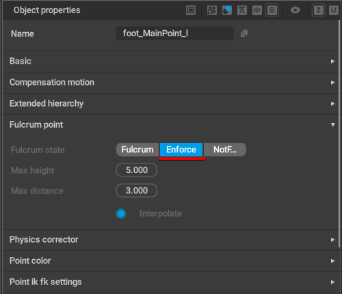
This setting can be found on the Object Properties panel, under the Fulcrum point tab.
A similar effect might occur when the character performs a kick. Here, the left foot rotates, leaving only the heel point as the fulcrum:
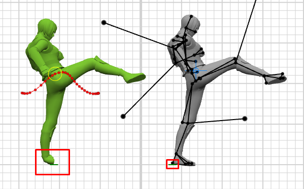
This can also be fixed by enabling Enforce for the heel controllers.
Another way is to increase the Max distance parameter:
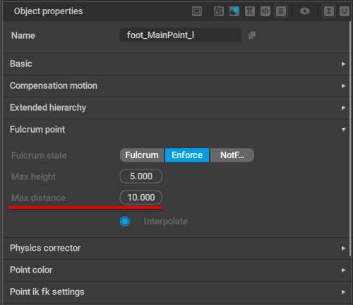
This parameter defines how far the Point Controllers can shift while still remaining fulcrum points:
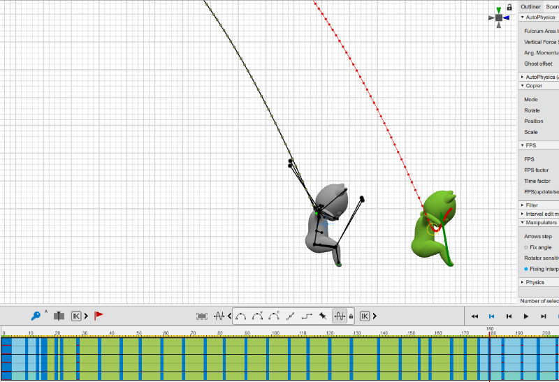
Timing Issues
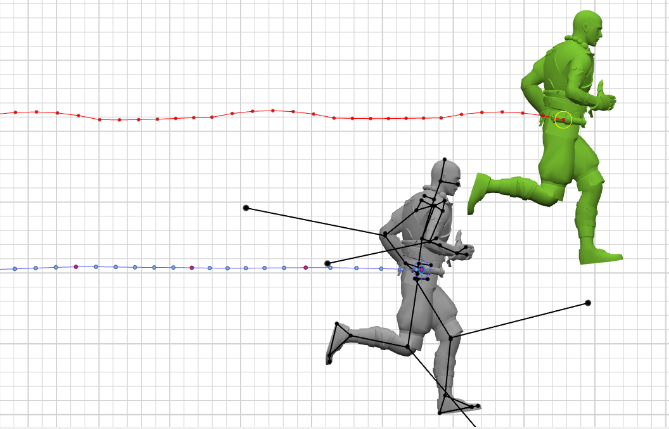
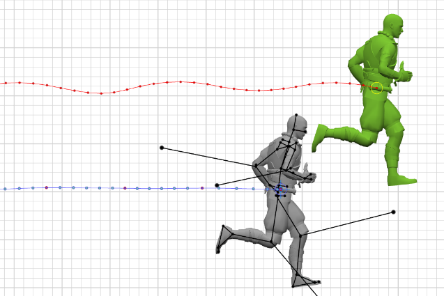
Sometimes AutoPhysics can cause distortions like this:
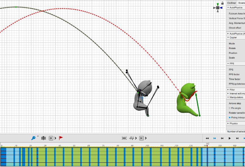
Take a note of the difference in the position of the character’s legs on the simulation in comparison with original animation.
This happens because AutoPhysics does not have enough frames to better position the character. To improve the situation:
1. Remove the Ballistic trajectory.
It is not required, but recommended to avoid complications.
2. Use Tracks stretching mode to increase the length of the part of the animation that displays this issue (the landing sequence in our example).
3. Set Bezier interpolation for the stretched intervals (or Bezier Clamped for feet and such).
4. Create a new Ballistic trajectory and snap the character to it.
As you can see, the stretched animation is significantly longer than the original (over 200 frames instead of about 165). However, because of that the AutoPhysics is able to display a solution much closer to the original.