
The Quick Rigging Tool won’t work for non-humanoid characters, so you’ll have to manually create every element of the rig.
To create rig controllers, you’ll need a model with a skeleton made up of Joints, and a mesh skinned to these Joints. Scenes in both FBX and DAE formats are supported.
To test the tools described in this tutorial, you can use this scene.
- Open a new scene.
- Add a model for rigging to the scene.
- Go to the Rig Mode.
The Rig Mode is a dedicated mode that allows you to create and edit elements of the character rig. There are no animation frames in this mode.

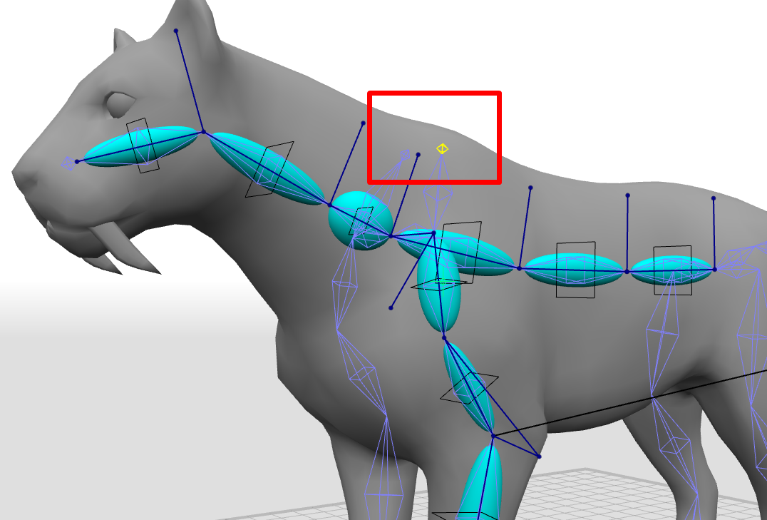
Rigs in Cascadeur include special Rigid Bodies (blue ellipsoids) that facilitate physically accurate behavior for the character.

One rig element includes:
- Three Point Controllers: Main, Additional and Direction.
- One Box Controller.
- One Rigid Body.
If the joint has more that one child, you’ll have to select one of them in order to set the direction.

Rig elements can be created for every Joint in the chain…

…or you can create one rig element for several joints:

The Additional Point handels the rotation for the corresponding element of the rig.

To conveniently control rotation with the Additional Point, it is important to choose an appropriate axis for it to lie on.The axis can be selected on the Rigging tools panel at the left side of the window.

The axis can be set either in world space, or in local space (i.e. the object’s own coordinate system).

You can also set the distance to the Additional Point from the corresponding Main Point. In most cases, the best option for placing the Additional Point is making it face upward or forward. It is also important to make sure the Additional Point does NOT lie on the line between the Main and the Direction Point.
It is important to create rig elements in the right order, as this is what defines their hierarchy. At the same time, the hierarchy of the rig elements can be different from the joint hierarchy!
We recommend to start creating the rig from the character’s pelvis, or from the joint at the top of the list in the Outliner. Such a joint, however, should also be a part of the character’s body.
Here are examples of such joint in various models:


Look how for this model, fist joint in the hierarchy are the Frog and D_Root joints - but these joints are not parts of the character and thus should not be included in the rig.

In some rigs, there can be a joint chain in the spine and another one in the tail, both having the same origin. When this is the case, make sure there are no Rigid Bodies with zero lengths: having them would lead to errors when the rig is generated.
So before anything else we should create rig elements for the spine.
- Hold the Shift key and select the joint in the pelvis, and after it, the joints in the spine.
- Select an axis fitting for the Additional Point.
- Click the Add Rig Element button

Sometimes, rig elements might end up too tiny to conveniently work with; in such cases, you can select the next joint to set up direction.
If you need to remove a rig element, use the Delete Rig Element button.

- Create rig elements for the spine.

The character’s head includes multiple joints for controlling jaws, eyes, ears and other parts of the face. When you create a controller for the head, it is important to select the particular joint that controls the head’s rotation as a whole.
If the character is symmetrical, it’s enough to only rig the limbs on one of the two sides. Then, we can easily mirror them.
- Create rig elements for the limbs on one of the sides.
In this example with the dinosaur, we’ve created rig elements only for one of the toes. Later, we’ll demonstrate how all three toes can be handled with only one controller.
Whether you should or shouldn’t add rig elements for the toes, this depends mostly on the characteristics of the particular character model. When toes are large, and the creature leans on them as it walks, you should rig them with every type of rig element. But when the toes play a secondary role, it might be enough to only create Box Controllers for them.
Some creatures might have two joint chains in their forelimbs: one going to the foot and another going to the clavicle. In such cases, we do not recommend creating rig elements for the clavicles.
Usually, a limb only bends across one of three axes. To set a bending axis:
- Hold Shift and select two Additional Points attached to the rig elements on both sides of the place where the limb should bend.
- Open the Hinge actions tab and click the Union to hinge button.

This way, you’ll join these points, as if creating a ball-and-socket connection for the limb.
Sometimes, the structure of the limb would imply several such connections in succession. For a case like this:
- Select the rig elements for the next part of the limb.
- Open the Proto Union Behavior tab in the Object Properties panel.
- Enable the Is additional hinge option.

It is also crucial to make sure that the Additional Points are on the same side as the ones in the preceding hinge connection. If they are not, you can
- Select the point in the second hinge
- Сopy its position (Ctrl + C)
- Choose global manipulator mode and paste its position (Ctrl + V). Don't remove the selection!
- Choose local manipulator mode
- Move the point toward the side along the desired axis of the local manipulator
Oftentimes, smaller elements such as fingers or ears do not contribute to the character’s mass or physical behavior in a significant way. This means that in order to simplify the physical rig - and to improve physics tools’ performance - you can forgo creating Rigid Bodies for body parts like these. These elements can be rigged with just Box Controllers.
- Enable the Only box controllers option on the Rigging tools panel.
- Create Box Controllers for smaller parts of the character.

- If you need to add a rig element for every selected joint, enable the Multiple Create option.
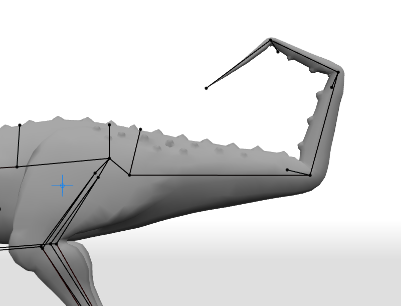
If your character has a long tail that includes a high number of Joints, it would be convenient to create a Spline Controller for it.
Such a controller would allow reducing the number of points you’d need to control the tail while fully retaining its flexibility.
Important note: the distance between the joints will change a little as they follow the spline.
Create rig elements for the tail. When you do this, you can actually skip some of the joints to reduce the amount of controllers. *creating a rig element for every joint in the chain makes using a Spline Controller somewhat pointless.

- Hold Shift and select every Proto Union element (click the blue-colored ellipsoids to do this).
- Without canceling selection, continue to hold Shift and add to the selection the Direction Point attached to the last element in the chain.
- Without canceling selection, switch to the Joint Mode.
- Hold Shift once again and add every Joint in the tail to the selection.
- Go to the Main tab on the Rigging tools panel and click the Add button in the Spline IK category.

Before we can mirror the character’s limbs and then finalize the rig, we need to set masses for the character’s body parts.
Masses of various body parts would influence the position of the Center of Mass and the character’s physical behavior.
You don’t have to be too precise with masses. Estimating approximate values for various body parts should suffice. Similarly. the sizes of the Rigid Bodies should roughly match the borders of the 3d mesh.
- Select the Rigid Body (blue ellipsoid).
- Open the Proto Union Behavior tab on the Object Properties panel.
- Set the mass for this body part in the Mass field.
- To change the size of the Rigid Body, set different values in the Width rigid body field and see how changing the parameter affects the appearance of the body in the Viewport.

Now we need to mirror rig elements we’ve created for the limbs. First of all, we’ll have to set a general mirroring plane fitting for this particular character. This is necessary so we could correctly mirror animation poses later, when the rigging is complete.
Next, we can set a mirroring plane for individual elements. Usually - but not always - such a plane would coincide with the general plane.
- Select the general mirroring plane (for the dinosaur scene, this would be the YZ plane).
- Open the Mirror Group tab on the Rigging tools panel.
- Set the mirroring plane.
- In the Original field, enter the designation for the side which you’ve rigged.
- In the Mirrored field, set the designation for the opposite side.
To see how sides are designated in your model, you can click one of the joints and then look at its name on the Object Properties panel. Oftentimes, the right and the left are distinguished by using letters R and L. Keep in mind that upper- and lowercase letters, as well as underscore signs are taken into account.
Some examples of side designations would be: ‘r_’ and ‘l_’, ‘_R’ and ’_L’, ‘_Right’ and “_Left” and so on.
- Select the joins or rig elements to be mirrored.
- Click the Create mirror object button.
- Go back to the animation mode to finalize the rig and check if it works correctly.
Now, the rig is almost complete and we only need to do one little detail: we wanted to make all three toes on the dinosaur’s paw controllable with only one controller.
This is not always required, but there are times when such a solution can be quite convenient.
Currently, our rig includes Rigid Bodies and Point Controllers for the middle toe, while two others only have Box Controllers. To make all three toes work together, we need to set these Box Controllers as children of the main toe.
- Select the Box Controllers of the two side toes.
- Go to the Outliner.
- Hold the Right Mouse Button and in the Outliner, drag the selected boxes on top of the rig element for the middle toe.